
Dynamic distortion elimination for output audio

a dynamic distortion and output audio technology, applied in the field of audio signal processing, can solve the problems of limiting the acoustic design, affecting so as to improve the quality of output audio

Inactive Publication Date: 2011-10-25
GOOGLE TECHNOLOGY HOLDINGS LLC
View PDF3 Cites 266 Cited by
  • Summary
  • Abstract
  • Description
  • Claims
  • Application Information

AI Technical Summary

Benefits of technology

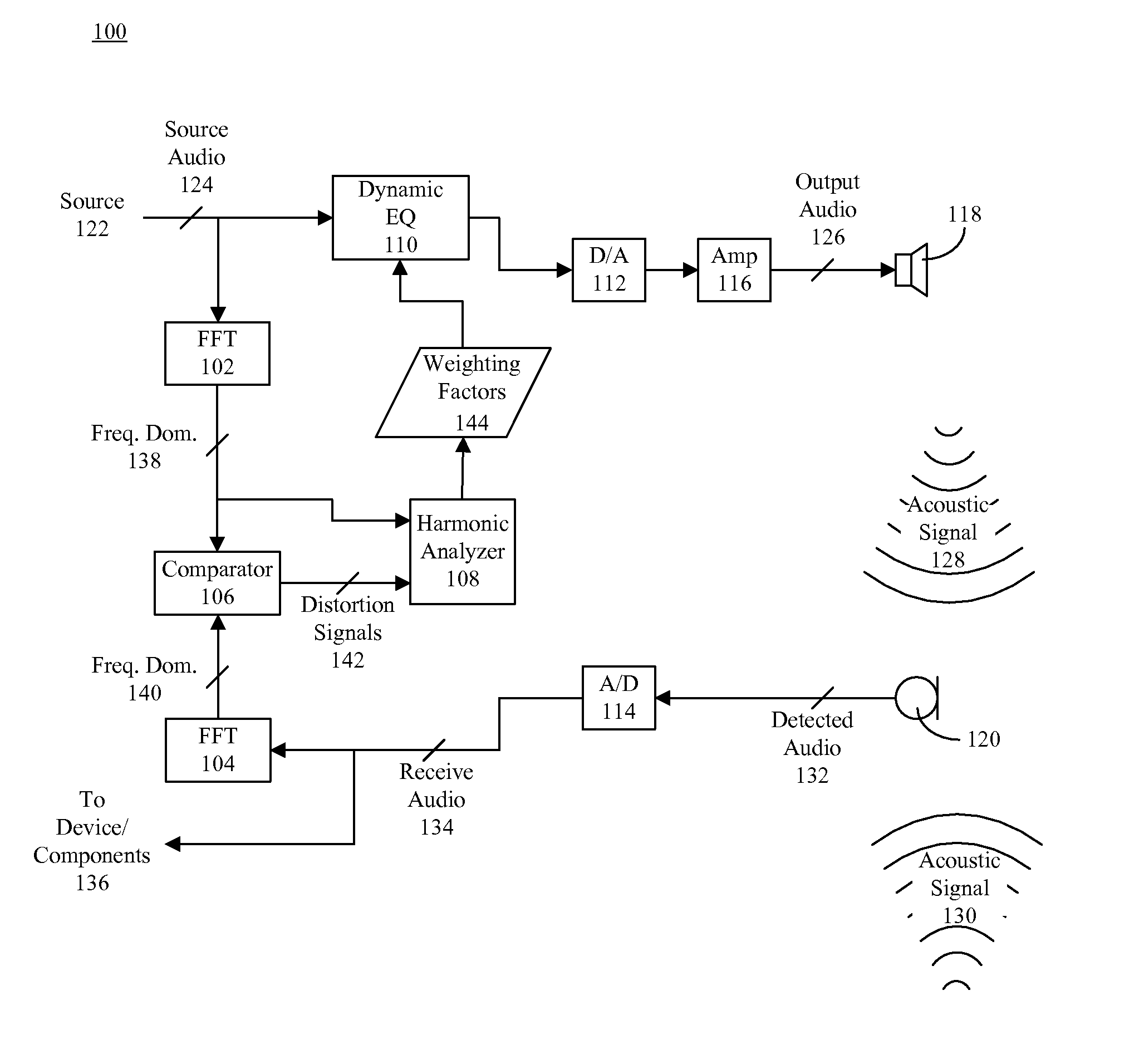
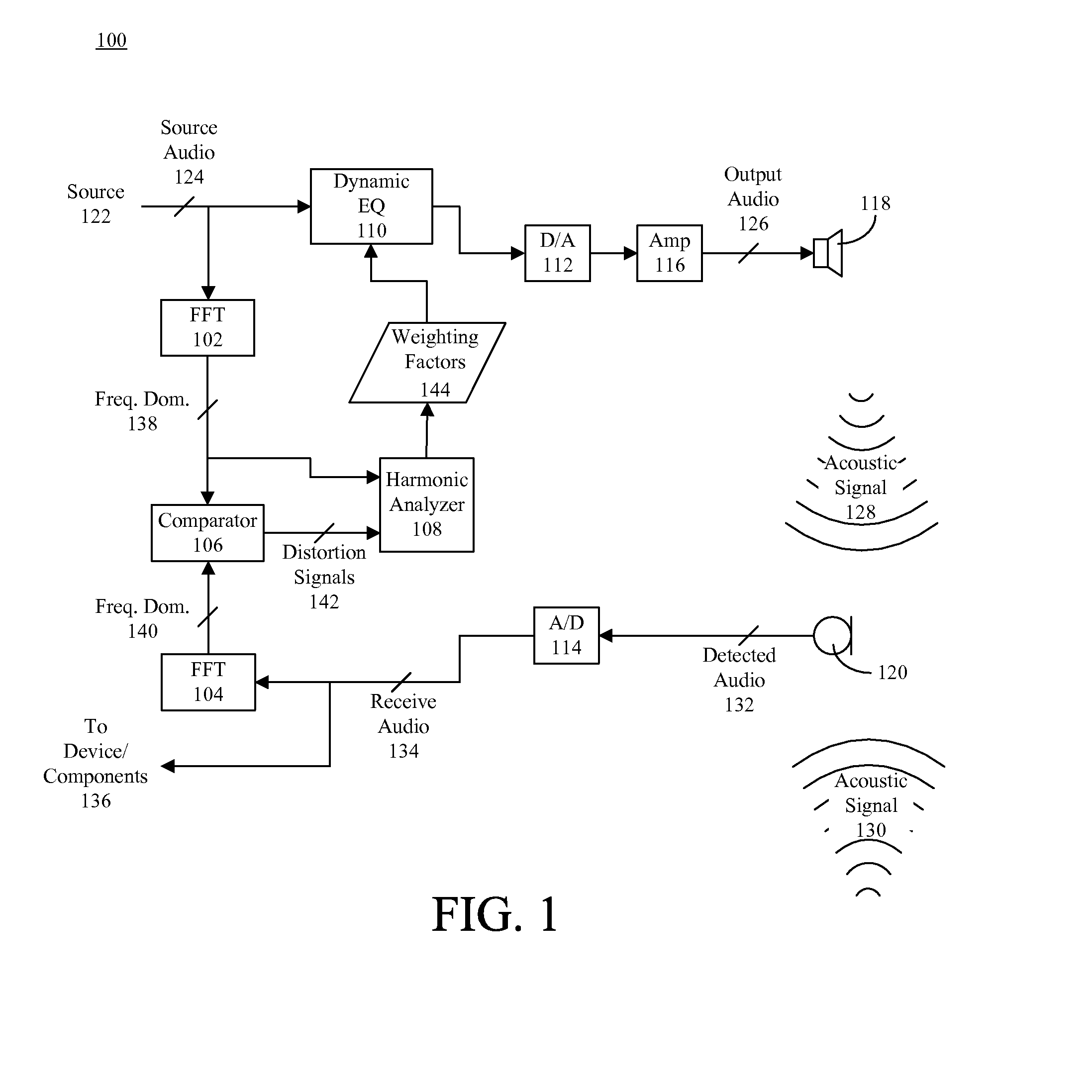
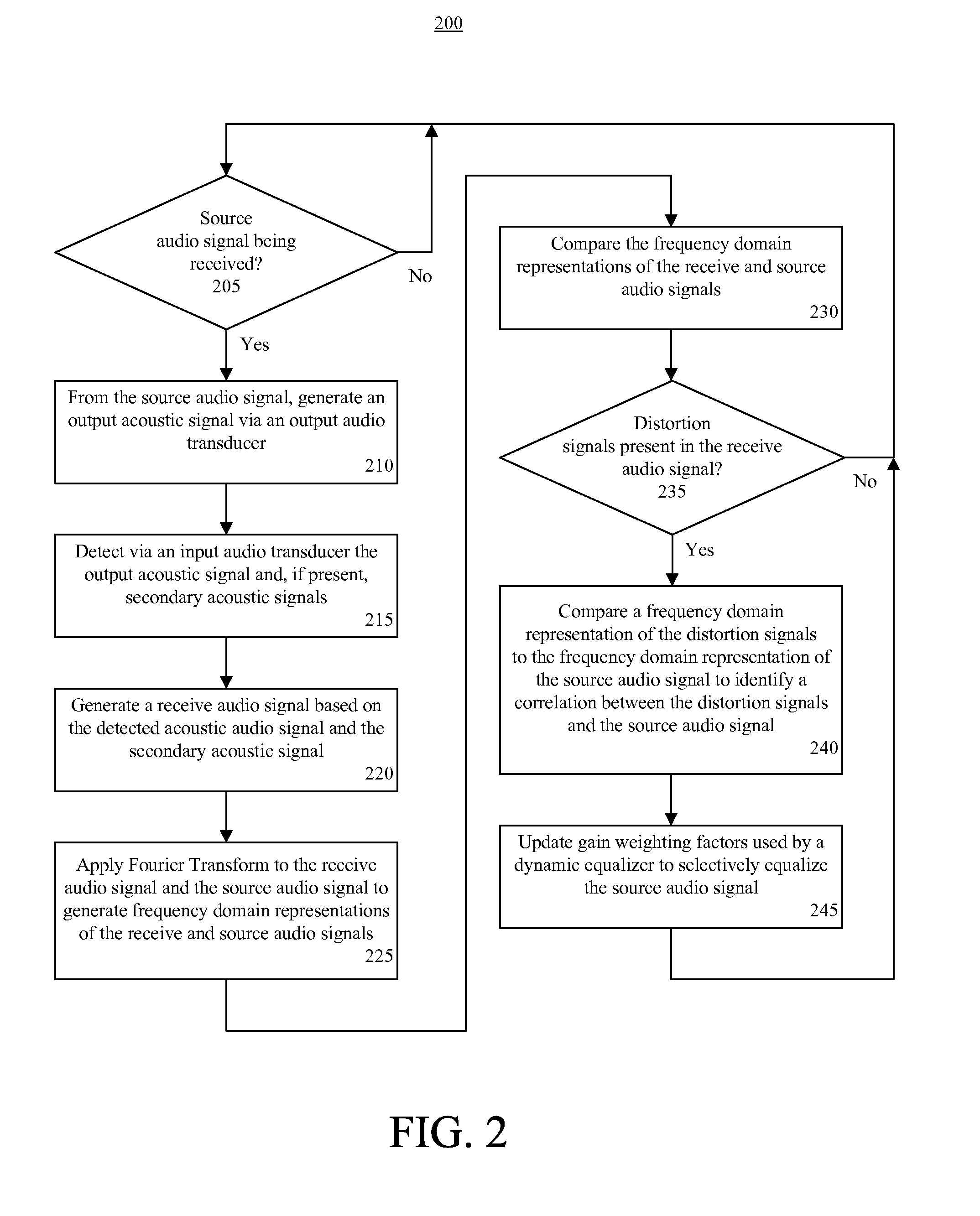
[0006]The present invention relates to a method for improving quality of output audio. The method can include detecting an output acoustic signal and generating a receive audio signal based, at least in part, on the detected output acoustic signal. The output acoustic signal can be generated via an output audio transducer of the device and detecting the output acoustic signal can include detecting the output acoustic signal via an input audio transducer of a device. Generating the receive audio signal further can include generating the receive audio signal based, at least in part, on a secondary acoustic signal generated by vibration of at least one device component.

Problems solved by technology

The design of high volume output audio transducers (e.g. loudspeakers) for small electronic devices is complicated.
Small size restrictions in a mobile station, for example, typically limit the acoustic design to using only a very small output audio transducer.
In this situation, it is not uncommon to have mechanical components within mobile station housing resonate due to vibration of the output audio transducer, which distorts the net sound being emanated by the mobile station.
Moreover, the resonant frequencies tend to shift over time due to components of the device loosening, grommets decaying, and general aging of the device.
Thus, the use of conventional equalization techniques fails to insure long term acceptable sound quality from a small electronic device.

Method used


Image

  • Dynamic distortion elimination for output audio
  • Dynamic distortion elimination for output audio
  • Dynamic distortion elimination for output audio

Examples


Embodiment Construction

[0019]While the specification concludes with claims defining features of the invention that are regarded as novel, it is believed that the invention will be better understood from a consideration of the description in conjunction with the drawings. As required, detailed embodiments of the present invention are disclosed herein; however, it is to be understood that the disclosed embodiments are merely exemplary of the invention, which can be embodied in various forms. Therefore, specific structural and functional details disclosed herein are not to be interpreted as limiting, but merely as a basis for the claims and as a representative basis for teaching one skilled in the art to variously employ the present invention in virtually any appropriately detailed structure. Further, the terms and phrases used herein are not intended to be limiting but rather to provide an understandable description of the invention.

[0020]The present invention relates to a method and a system for improving ...


PUM


Abstract

A method (200) for improving quality of output audio (126). The method can include detecting an output acoustic signal (128) and generating a receive audio signal (134) based, at least in part, on the detected output acoustic signal. A frequency domain representation (140) of the receive audio signal can be compared to a frequency domain representation (138) of a source audio signal (124) from which the output acoustic signal is generated. At least one distortion signal (142) in the receive audio signal can be identified, and the source audio signal can be selectively equalized to reduce an amplitude of the source audio signal at a frequency that correlates to the distortion signal.

Description

BACKGROUND OF THE INVENTION[0001]1. Field of the Invention[0002]The present invention generally relates to audio signal processing.[0003]2. Background of the Invention[0004]The design of high volume output audio transducers (e.g. loudspeakers) for small electronic devices is complicated. Small size restrictions in a mobile station, for example, typically limit the acoustic design to using only a very small output audio transducer. Nonetheless, high output audio levels are required to use the mobile station in speakerphone mode, which necessitates driving the output audio transducer with relatively high power. In this situation, it is not uncommon to have mechanical components within mobile station housing resonate due to vibration of the output audio transducer, which distorts the net sound being emanated by the mobile station.[0005]In an attempt to minimize the effect of resonances, a designer of an electronic device may implement conventional equalization techniques to equalize au...

Claims


Application Information

Patent Timeline
Patent Type & Authority Patents(United States)
IPC IPC(8): H03G3/20
CPCH03G3/32H03G5/165
Inventor BURGAN, JOHN M.KORNELUK, JOSE E.NELSON, GLENN R.PULIDO, MARCO
Owner GOOGLE TECHNOLOGY HOLDINGS LLC
Learn More