Backlight apparatus and display apparatus using same

a backlight apparatus and display device technology, applied in lighting and heating devices, planar/plate-like light guides, instruments, etc., can solve the problems of uneven optical properties, inability to compact backlight devices, and inability to reduce the efficiency of so as to suppress uneven optical properties of reflectors, easy and efficient insertion and replacement of reflectors

Inactive Publication Date: 2011-10-25
FUNAI ELECTRIC CO LTD
View PDF8 Cites 0 Cited by
  • Summary
  • Abstract
  • Description
  • Claims
  • Application Information

AI Technical Summary

Benefits of technology

[0017]To cope with the conventional problems mentioned above, it is an object of the present invention to provide a backlight apparatus which allows easy and efficient insertion and replacement of a reflector and which suppresses unevenness in the optical properties of the reflector.
[0022]With the first structure according to the present invention, because the reflector guide having a tilted surface tilted toward the inserting direction of the reflector is formed on the side wall of the housing, an end portion of the reflector slides along the tilted surface and is guided into the housing. Thus the reflector is easily inserted into the housing and the reflector replacing efficiency is improved.
[0023]Further, after the reflector is inserted, because the reflector is supported tightly by the reflector guide in the direction perpendicular to the inserting direction, the reflector is securely retained in the housing, and unevenness in the optical properties can be suppressed.
[0024]In addition, when the reflector guide is formed lower than the side wall of the housing, a space through which the lead can pass is ensured between the upper surface of the reflector and the upper surface of the housing. Thus when the reflector is built in, the lead is not sandwiched nor damaged between the side wall of the housing and the side surface of the reflector. Moreover, the reflector guide is designed as small as possible taking into account the thickness of the lead, which allows the backlight apparatus to be compact.
[0025]With the second structure according to the present invention, a plurality of reflector guides formed on the side wall of the housing securely retain the reflector in the housing, and unevenness of the optical properties can be curbed.

Problems solved by technology

Therefore, there has been a problem that the reflector 6 is not securely fixed in the housing 2 and unevenness in the optical properties is caused.
Also there has been a disadvantage that if the space between the side plate 6b of the reflector 6 and the side wall of the housing 2 is made small to make the lead 10b support tightly the side plate 6b of the reflector 6, the lead 10b can be damaged and the efficiency of insertion and replacement of the reflector can be lowered.
However, according to the invention described in JP-A-H11-134921, because the lamp cover needs to be disposed between the side wall of the housing and the reflector, the backlight apparatus cannot be made compact and the insertion of the reflector cannot be carried out efficiently.

Method used


Image

  • Backlight apparatus and display apparatus using same
  • Backlight apparatus and display apparatus using same
  • Backlight apparatus and display apparatus using same

Examples


Embodiment Construction

[0037]Hereinafter, an embodiment of the present invention will be explained referring to the drawings. The portions which are the same as or similar to those in FIGS. 5-8 showing the conventional apparatus are numbered with the same numerals and the description of them is omitted. In these drawings, for easy understanding, the dimensional ratios of the members are different from the actual ones and the structure is schematically shown with details omitted.

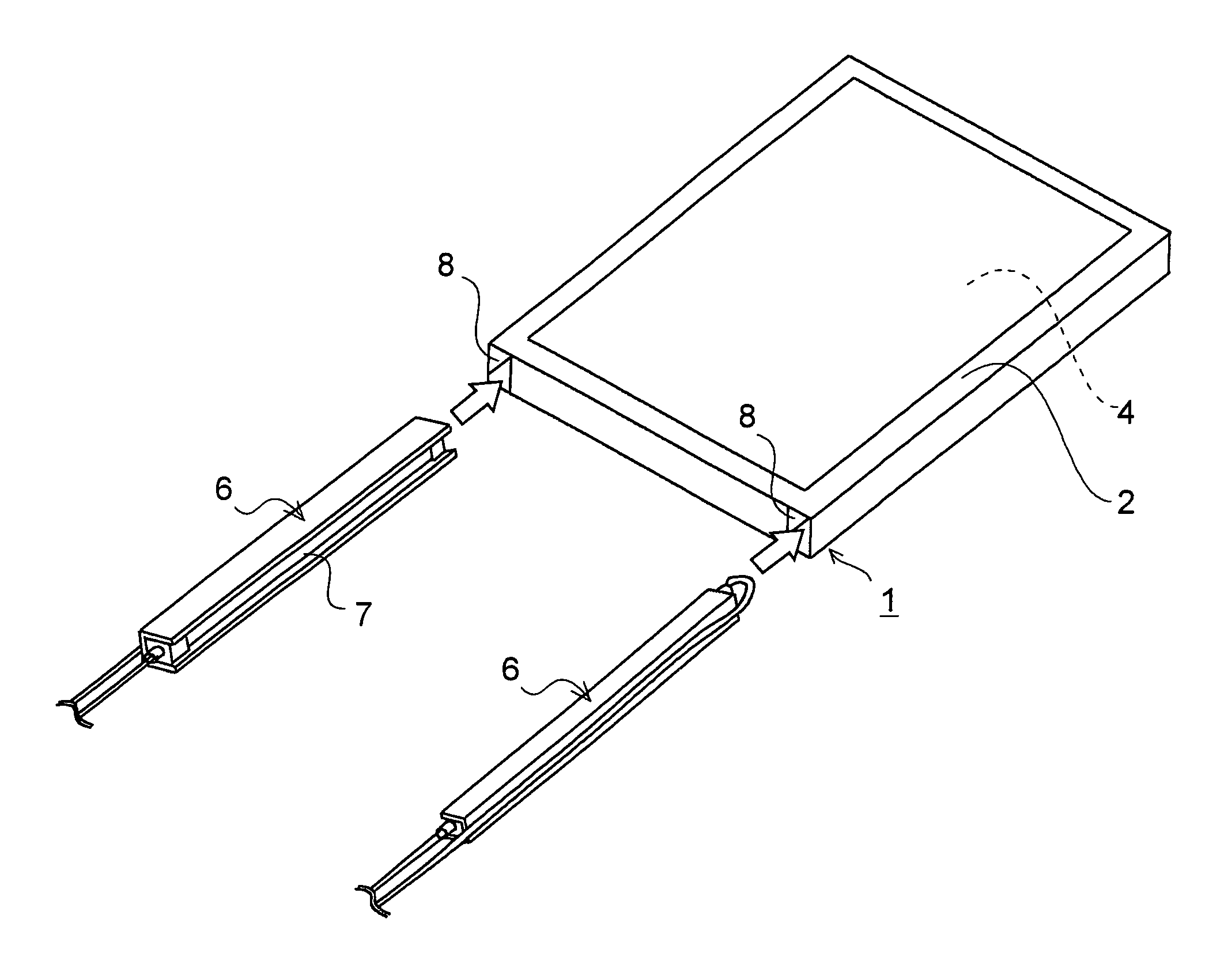
[0038]FIG. 1 is an exploded perspective view showing a state before the reflector 6 is built in a backlight apparatus according to an embodiment of the present invention. Like the conventional apparatus shown in FIG. 5, the backlight apparatus according to the embodiment of the present invention has the structure in which the optical sheet 3 is laminated on the upper surface of the light guide plate 4 and the reflecting sheet 5 is laminated on the lower surface of the light guide plate 4. The reflector 6 (not shown in FIG. 1) retai...


PUM

PropertyMeasurementUnit
weightaaaaaaaaaa
optical propertiesaaaaaaaaaa
thicknessaaaaaaaaaa

Abstract

A backlight apparatus has a housing composed of a first frame and a second frame, each having a side wall, put together, an optical guide plate housed in the housing, and a reflector inserted between the side surface of the light guide plate and the side wall of the housing. A reflector guide is formed on the side wall of the housing, and has a tilted surface tilted toward an insertion direction of the reflector.

Description

[0001]This application is based on Japanese Patent Application No. 2007-140486 filed on May 28, 2007, the contents of which are hereby incorporated by reference.BACKGROUND OF THE INVENTION[0002]1. Field of the Invention[0003]The present invention relates to a backlight apparatus, more particularly to a technology which improves ease of insertion and replacement of a reflector including a light source in a backlight apparatus.[0004]2. Description of the Prior Art[0005]In recent years, flat panel displays are becoming the mainstream and expanding their market instead of cathode ray tubes which have been conventionally used as display apparatuses. Among others, liquid crystal displays (LCDs) are characterized by their thinness, light weight, low power consumption, and high definition, and have been widely used in the fields of televisions, personal computers and the like.[0006]An LCD display usually comprises: an LCD module composed of an LCD panel—having a pair of mutually facing elec...

Claims


Application Information

Patent Timeline
Patent Type & Authority Patents(United States)
IPC IPC(8): G02F1/1335
CPCG02B6/009G02F1/133605G02F1/133608G02B6/0031G02B6/0071G02B6/0091
Inventor TANAKA, MITSURU
Owner FUNAI ELECTRIC CO LTD
Why Eureka
Try Eureka