A fully automatic cable laying machine

A fully automatic technology for cable laying, which is used in cable laying equipment, thin material handling, and conveying filamentous materials, etc. It can solve the problems of heavy weight, inconvenient cable laying, and difficulty in realizing automatic cable transmission and laying.

Active Publication Date: 2021-09-21
嘉兴市平安电气工程有限公司
View PDF15 Cites 0 Cited by
  • Summary
  • Abstract
  • Description
  • Claims
  • Application Information

AI Technical Summary

Problems solved by technology

In the construction work of cable laying, it is necessary to carry out the loading, transportation and retracting of the cable reel. The existing cable reel loading and unloading work is carried out manually, which consumes a lot of manpower. It is difficult for the cable reel to be easily and smoothly transferred to the cable. Cable unwinding on the reel unwinding mechanism is not conducive to the realization of full automation of cable laying. Conventional cables are heavy-duty cables, so the cable reel is large in size and heavy in weight, which brings a lot of inconvenience to manual operation. In the existing In the work of cable retraction, the cable is also laid by manpower. The frictional resistance of the cable on the ground is large, which brings inconvenience to the laying of the cable and increases manpower consumption. The contact causes intense friction between the cable and the ground, resulting in serious consequences such as scratches and damages during the transmission process of the cable. The existing cable is not equipped with a guide mechanism during the laying process to effectively guide and support the power cable during the transmission process. protection, it is difficult to realize the smooth and smooth automatic transmission and laying of cables, which cannot meet the needs of cable laying and use

Method used


Image

  • A fully automatic cable laying machine
  • A fully automatic cable laying machine
  • A fully automatic cable laying machine

Examples


Embodiment Construction

[0028] In order to further describe the present invention, a specific implementation of a fully automatic cable laying machine will be further described below in conjunction with the accompanying drawings. The following examples are explanations of the present invention and the present invention is not limited to the following examples.

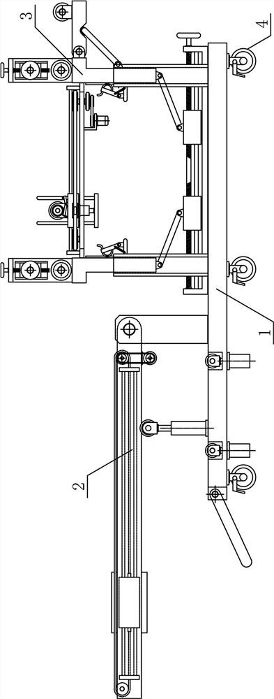
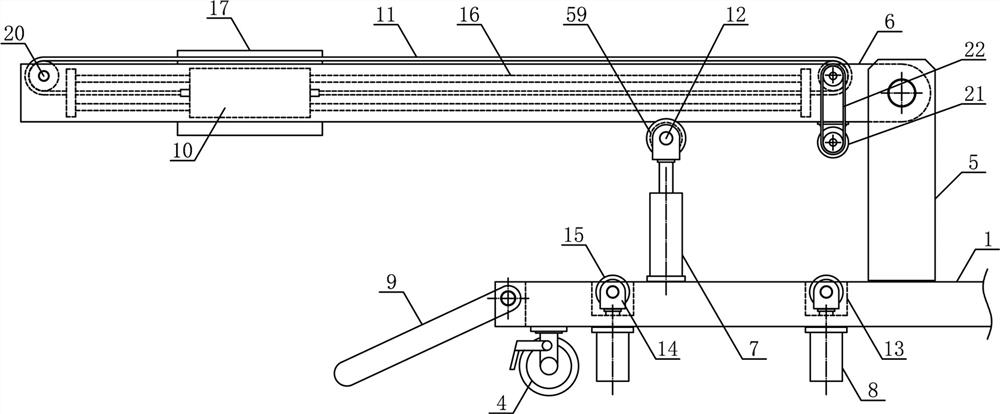
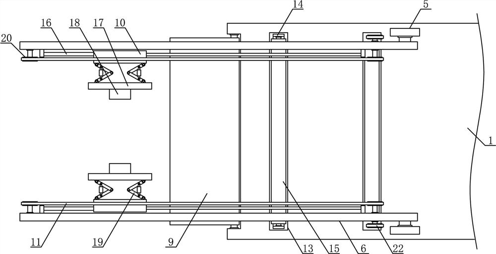
[0029] Such as figure 1 As shown, a fully automatic cable laying machine of the present invention includes a cable laying base 1, a cable reel feeding mechanism 2 and a cable pulling and laying mechanism 3, and the cable reel feeding mechanism 2 and the cable pulling and laying mechanism 3 are horizontally The direction is fixedly arranged on both sides above the cable laying base 1 in turn, and a plurality of universal wheels 4 with brakes are uniformly arranged on the lower side of the cable laying base 1, such as figure 2 with image 3 As shown, the cable reel feeding mechanism 2 of the present invention includes a feeding fixed bracket ...


PUM


Abstract

The invention discloses a fully automatic cable laying machine, which belongs to the field of electric power engineering equipment. The cable reel feeding mechanism and the cable pulling and laying mechanism included in the invention are fixedly arranged on both sides above the cable laying base in sequence along the horizontal direction, and the two sides above the cable laying base are respectively symmetrically provided with feeding and pulling rotating plates, and the reel is lifted. The output end of the air cylinder is horizontally connected with the supporting roller rotating bracket, and the reel lifting supporting roller is connected horizontally. The middle part of the reel pulling plate on the side of the feeding pulling guide plate is horizontally fixed with a reel limit card tube, and the bearing on the upper side of the lifting guide plate Supporting guide rollers are horizontally connected to the support bracket, and the cable pulling mechanism is fixed horizontally between the lifting guide plates on both sides above the cable laying base. The invention has a reasonable structural design, can efficiently and stably automatically pull and feed the cable reel, and can conveniently and smoothly continuously pull and lay the cable, thereby improving the automation of cable laying and meeting the needs of use.

Description

technical field [0001] The invention belongs to the field of electric power engineering equipment, in particular to a fully automatic cable laying machine. Background technique [0002] With the rapid development of modern city construction and economy, cables are widely used in daily production and life. Cables can mainly be used in power systems, information transmission systems and instrument control systems. Cable laying refers to laying along surveyed routes, The process of installing cables to form cable lines, according to the use occasions, cable laying can be divided into several laying methods such as overhead laying, underground pipeline laying, direct burial laying, underwater laying, wall laying and tunnel laying. It is very important to ensure the transmission quality, reliability and construction maintenance of the line. In the construction of urban power distribution network, it is necessary to carry out the construction of power cables for distribution netwo...

Claims


Application Information

Patent Timeline
Patent Type & Authority Patents(China)
IPC IPC(8): B65H49/30B65H49/38B65H57/28H02G1/06
CPCB65H49/30B65H49/38B65H57/28B65H2701/34H02G1/06
Inventor 方建清方浩黄伟强
Owner 嘉兴市平安电气工程有限公司
Why Eureka
Try Eureka