
Device and method for the detection of particles

a technology for particle detection and detection chambers, applied in the field of devices and methods for particle detection, can solve the problems of difficult “on-site” measurement (e.g. bedside testing), high analysis cost, and small analytical instruments based on these efforts, and achieve the effect of reducing the distance between the first and second walls and reducing the volume of the detection chamber

Active Publication Date: 2011-10-18
CLONDIAG GMBH
View PDF4 Cites 16 Cited by
  • Summary
  • Abstract
  • Description
  • Claims
  • Application Information

AI Technical Summary

Benefits of technology

[0114]One advantage of the present invention refers to the fact that sample volumes of less than 10 μl can be analyzed. Typically, sample volumes are in a range of 1 to 1.000 μl, preferably in a range of 1 to 100 μl, more preferably in a range of 1 to 25 μl, and most preferably in a range of 1 to 5 μl.
[0115]The samples to be analyzed can be introduced into the reaction chamber without any further purification, since the inventive device and method are specifically designed to allow the qualitative and / or quantitative detection of any particles in a given sample without the requirement to perform washing and rinsing steps. However, in some cases it might be preferable to purify the sample, at least partially, for example in order to remove any crude contaminations that would otherwise interfere with further detection. Such (partial) purification of the sample can be accomplished in different ways, for example by filtration of the sample before introducing it into the reaction chamber.
[0116]Furthermore, it may be required to dilute a sample to be analyzed due to a comparably high viscosity that would otherwise interfere with the diffusion of the sample throughout the reaction chamber of the inventive device. Dilution of the sample can be easily achieved by adding a diluent to the sample. Examples of suitable diluents include inter alia water, organic and inorganic solvents, phosphate-buffered saline and the like. The diluent may be added before introducing of the sample into the device or may be directly added into the filling unit and / or the reaction chamber, as described above.
[0117]After the sample, and optionally any additional reagents, have been introduced into the reaction chamber or have been transferred from the one or more filling units into the reaction chamber, the sample may optionally be incubated in the reaction chamber for a given period of time to allow proper diffusion throughout the reaction space. Typically, the incubation period is in the range of 1 s to 30 min, preferably in the range of 10 s to 15 min, and particularly preferably in the range of 30 s to 10 min.
[0118]In some preferred embodiments, the method according to the present invention further comprises introducing one or more agents each comprising one or more detectable moieties into the reaction chamber of the device before performing step (b). That is, the agents comprising one or more detectable moieties may be introduced into the reaction chamber before introducing the sample, concomitantly with the sample, or after the sample has been introduced either directly or via a filling unit, as described above.
[0119]The term “agent comprising one or more detectable moieties”, as used herein, refers to any compound that comprises one or more appropriate chemical substances or enzymes (i.e. one or more “moieties”), which directly or indirectly generate a detectable compound or signal in a chemical, physical or enzymatic reaction. Such an agent may thus be necessary for or will facilitate detection of one or more species of particles of interest by being capable of forming interactions with said particles.

Problems solved by technology

However, conventional flow cytometry systems remain largely inaccessible for routine clinical use due to typically bulky instrumentation, which does not only make “on-site” measurements (e.g. bedside testing) difficult but also gives rise to high costs per analysis.
Analytical instruments based on these efforts are smaller and more portable than conventional devices.
However, all these devices and methods described above require comparably sophisticated detection techniques, which are expensive both in terms of initial cost and maintenance of the necessary analytical instrumentation as well as require highly trained personnel.
This makes the conventional systems unsuitable for routine medical practices, “bedside” testing, or in remote locations.

Method used


Image

  • Device and method for the detection of particles
  • Device and method for the detection of particles
  • Device and method for the detection of particles

Examples


example 1

Determining the Presence of CD4+ Cells in Human Blood

[0157]The CD4+ cells of a human blood sample were labeled with anti-CD4 phycoerythrin-conjugated monoclonal antibody (CD4-PE) using the CD3CD4 kit (GE Healthcare Life Sciences, Heidelberg, Germany) according to the instructions of the manufacturer. In brief, 10 μl blood were mixed with 2 μl CD4-PE (1:25 diluted stock solution) and 2 μl 20 mM EDTA. Then, the mixture was incubated for 15 min in the dark.

[0158]The blood sample was diluted to a concentration of less than 500 cells / μl (a higher concentration would interfere with proper handling of the device) and analyzed in a reaction chamber configured as a capillary channel that is made of polydimethylsiloxane, i.e. an elastically deformable material. The reaction chamber is 2.048 mm×0.04 mm×24 mm in size and thus has a total volume of approximately 2 μl.

[0159]For introducing the sample 2.5 μl of the diluted blood sample were placed adjacent to the opening of the channel and introdu...

example 2

Comparison of Flow Cytometry and an Inventive Assay for Determining the Number of CD4+ Cells in Human Blood

[0162]In order to test the suitability of the inventive assay for quantitative analyses it was compared to conventional flow cytometry for determining CD4+ cell numbers in human blood. The CD4+ cells of a human blood sample were labeled as described in Example 1. Samples were analyzed using a Guava PCA flow cytometer (Guava Technologies, Inc., Hayward, Calif., USA; excitation wavelength: 532 nm, emission wavelength: 580-583 nm) according to the manufacturer's instructions as well as by an inventive assay as described in Example 1. The results are shown in FIG. 6 and represent mean values±SEM of 5-7 measurements. The results are expressed as numbers of CD4+ cells per μl blood.

[0163]The mean values obtained for the two methods as well as the respective differences in percent are also summarized in the following table.

[0164]

Assay no.Mean FlowMean AssayΔ [%]1123411149.782120813309....


PUM


Abstract

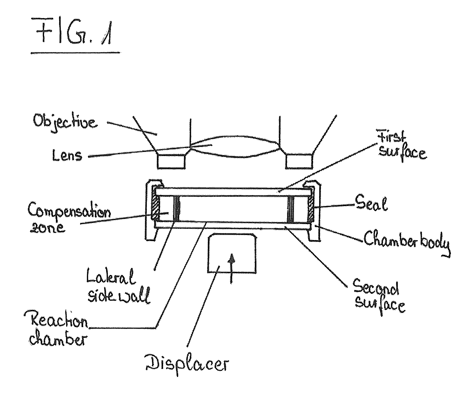
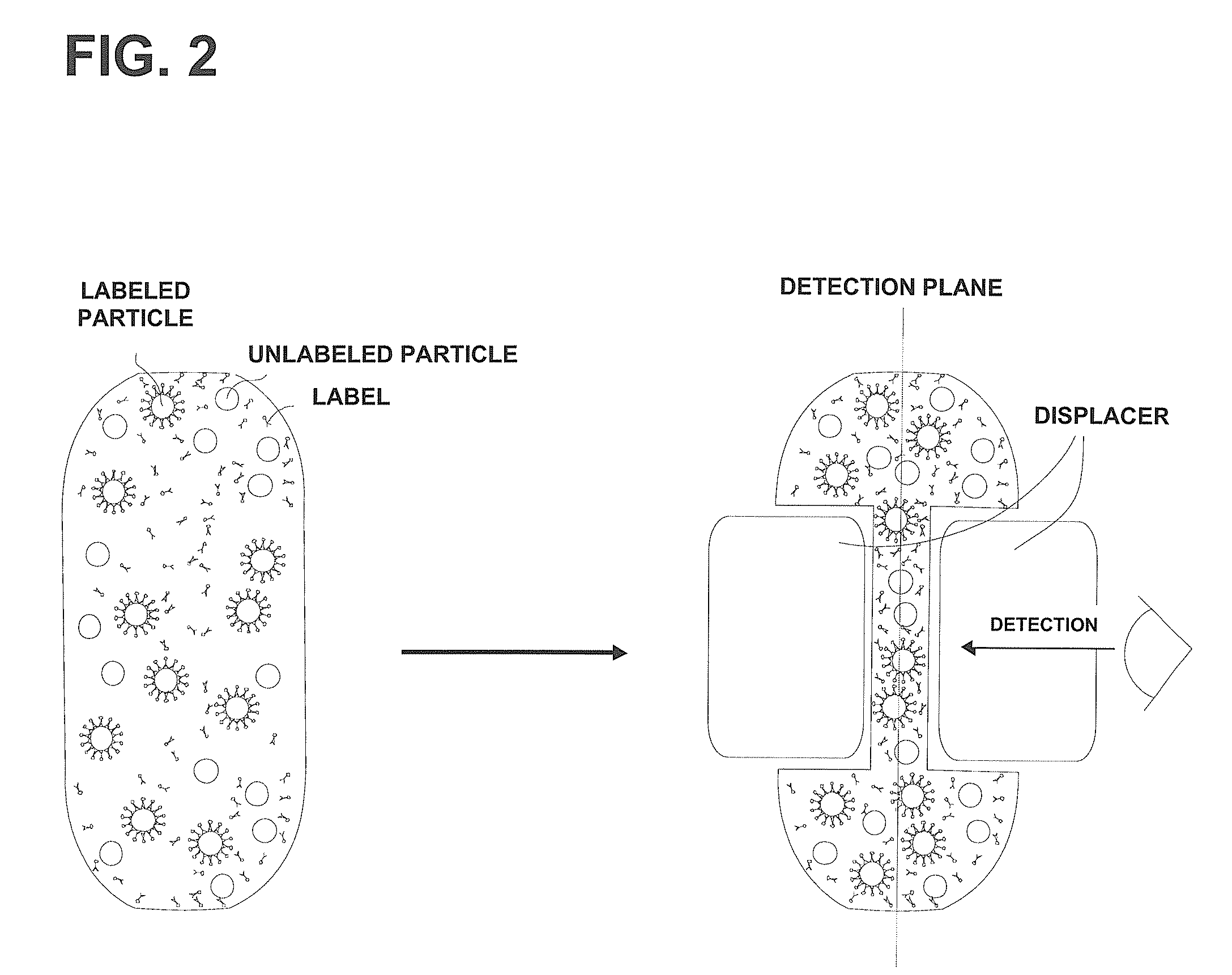
The present invention relates to devices and methods for the qualitative and / or quantitative detection of particles. In particular, the invention relates to devices for the detection of particles, comprising a reaction chamber formed within a chamber body between a first surface and a second surface, wherein the second surface is located opposite to the first surface, and one or more displacers, wherein the distance between the first surface and the second surface is variable via the one or more displacers at least in one or more parts of the surface area of the first surface and / or the second surface. The invention also relates to corresponding methods for the detection of particles, comprising positioning a sample supposed to comprise one or more species of particles to be detected in a reaction chamber, displacing at least a part of the sample within the reaction chamber via the one or more displacers; and detecting / determining a value indicative for the presence and / or number of one or more species of particles.

Description

CLAIM OF PRIORITY[0001]This application claims priority under 35 USC 371 to International Application No. PCT / EP2006 / 068153, filed on Nov. 6, 2006, which claims priority to German Application Serial No. 10 2005 052 752.3, filed Nov. 4, 2005, each of which is incorporated by reference in its entirety.RELATED APPLICATIONS[0002]This application claims the benefit of German patent application DE 10 2005 052 752, which is incorporated herein by reference in its entirety. The present application further relates to German patent application DE 10 2005 052 713 and to the International Patent Application entitled “Method and device for the detection of molecular interactions”, filed on Nov. 6, 2006 (Maiwald reference number: C 7794), both of which applications are incorporated herein by reference in their entireties.FIELD OF THE INVENTION[0003]The invention relates to devices and methods for the detection of particles.BACKGROUND[0004]The detection of the presence and / or the enumeration of ab...

Claims


Application Information

Patent Timeline
Patent Type & Authority Patents(United States)
IPC IPC(8): G06K9/74
CPCB01F11/0045B01F11/0266B01F13/0059B01L3/50273B01L3/502746G01N21/03G01N33/56966B01L2200/027B01L2300/0636B01L2300/0822B01L2300/0825B01L2400/0481G01N35/0099G01N2035/00346G01N2021/0346B01F31/31B01F31/86B01F33/30
Inventor ERMANTRAUT, EUGENBICKEL, RALFSCHULZ, TORSTENULLRICH, THOMASTUCHSCHEERER, JENS
Owner CLONDIAG GMBH
Learn More