
Electrophotographic developer and carrier therefor, core material particle for carrier for electrophotographic developer and production method thereof and image forming method

a technology which is applied in the field of electrophotographic developer and carrier, core material particle for carrier for electrophotographic developer and production method thereof, can solve the problems of developer still having unsolved, unsolved big issue, increase production cost, etc., and achieve excellent granularity, prevent the occurrence of carrier adhesion, and high image quality

Inactive Publication Date: 2011-10-18
RICOH KK
View PDF37 Cites 1 Cited by
  • Summary
  • Abstract
  • Description
  • Claims
  • Application Information

AI Technical Summary

Benefits of technology

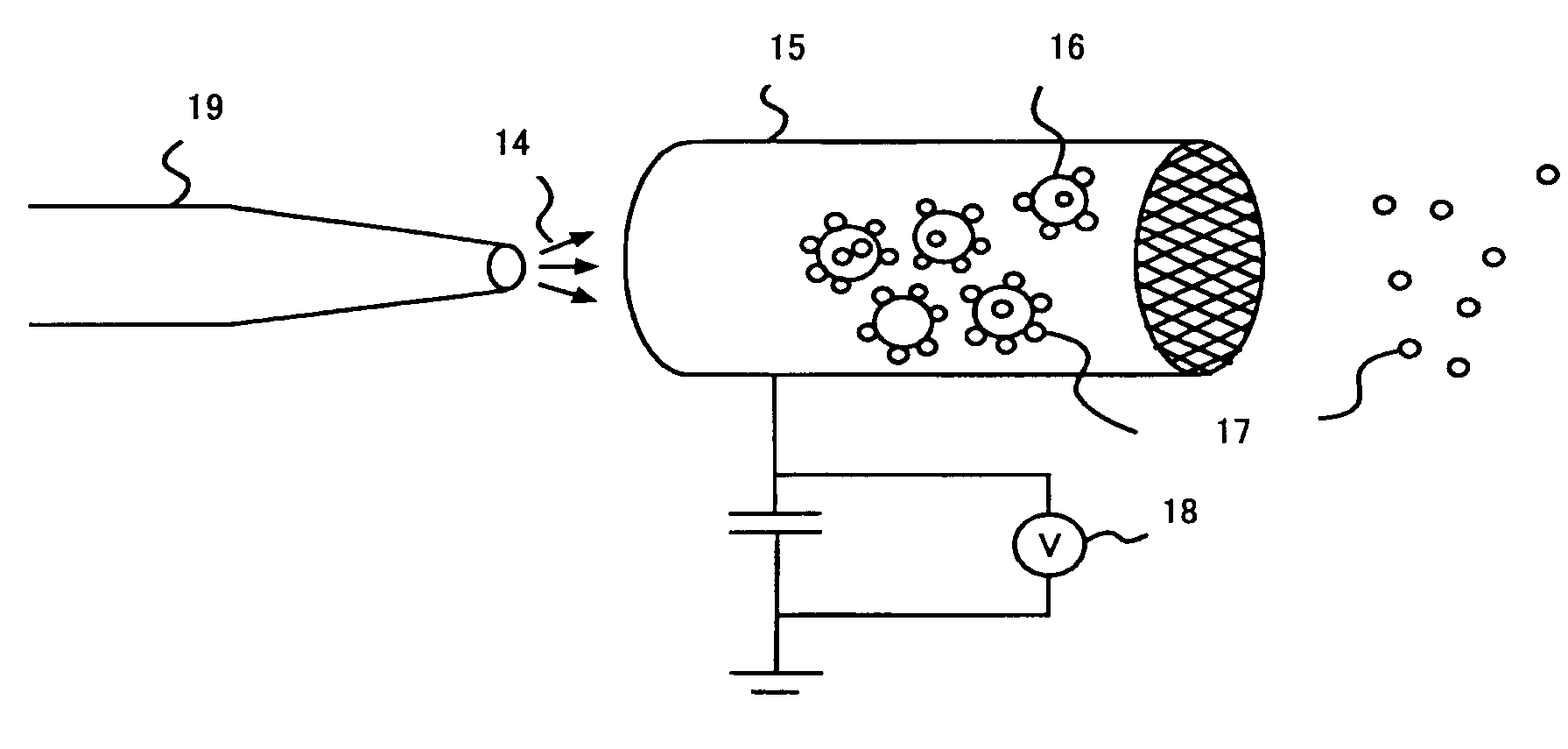
The present invention provides small diameter core material particles for electrophotographic carriers that can prevent problems such as carrier adhesion, high driving torque, and fluctuations in developer supply amount and image density. The core material particles have small BET specific surface areas and a narrow particle diameter distribution, which can be obtained with a low production cost using a pair of meshes. The carriers and developer produced using these core material particles provide high image density. The invention also provides a classification step for the core material particles to efficiently and cheaply produce them.

Problems solved by technology

From the aspect of the process, minimizing a developing gap, thinning a photoconductor and reducing a writing beam spot diameter are effective ways to correspond to such demands, but these ways increase the production cost and still have an unsolved big issue in, for example, reliability.
That using a small diameter toner in a developer can drastically improve the dot reproducibility is commonly known, however, that developer still has unsolved disadvantages in, for example, occurrence of background smears and inadequacy of image density.
And resins with a low flexibility point have been used for small diameter full color toners in order to obtain sufficient color tones, however, using the resins will cause an increase of carrier spent, deterioration of a developer, toner scattering and background smears to the full color toners compared with a black toner.
This magnetic carrier is, however, not coated with resin and is used under a low developing electric field applied thereon, and has disadvantages in that the carrier has poor developing ability and, because the carrier is not coated with resin, has a short operating life.
As a result, such conventional small diameter carriers cause flaws of a photoconductor / fixing roller, and have big issue in practical use.
However, it is commonly known that the sieve classification method has difficulties in producing smaller carrier particles with a narrow particle diameter distribution because of the reduction in the mass per particle.
Furthermore, smaller diameter carriers tend to have higher friction between particles and cause an increase in developing sleeve driving torque, resulting in scratching a surface of the sleeve and causing more toner fixations.
That increases in friction and torque cause fluctuations in supply amount of developer to the sleeve and in the image density.
Such carries having small diameters and BET specific surface areas, however, because of the smooth surface, or higher sphericity in the shape of the carrier particles, tend to be stuck in opens of the sieve, and thus obtaining the carrier particles from the sieve classification method has been particularly difficult.
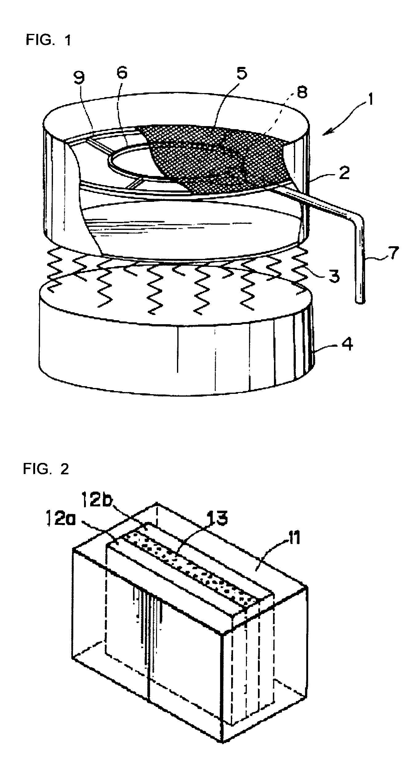
However, when the classification machine uses a mesh having small openings, since the mesh is made with thin material and thus strength thereof is weak (as the mesh material is made with thin threads), a part of the edge of the mesh can easily broken due to the weight of the carrier particles after being used for a long time, resulting in that unclassified fine particles are mixed into the classified carrier particles, increasing the content of the fine particles.
Furthermore, maintaining the classification performance over classification processes for particles having small particle diameters and BET specific surface areas is difficult even when a vibrating screen using the ultrasonic transducer equipped with the resonant ring is in use.
That is because of occurrence of mesh clogging that was particularly big issue.
Particles having small BET specific surface areas increase contact areas of the particles and the mesh threads and resistance of the particles to pass through the mesh, resulting in frequent occurrences of mesh clogging.
Smaller diameter particles have higher tendency to cause the mesh clogging.
When the mesh is clogged, as the carrier particles hide among the openings, it is quite difficult to remove the carrier particles, requiring an exchange of the mesh.
On the other hand, production costs of a stainless steel mesh having small openings are extremely high, resulting in higher carrier production costs.

Method used


Image

  • Electrophotographic developer and carrier therefor, core material particle for carrier for electrophotographic developer and production method thereof and image forming method
  • Electrophotographic developer and carrier therefor, core material particle for carrier for electrophotographic developer and production method thereof and image forming method
  • Electrophotographic developer and carrier therefor, core material particle for carrier for electrophotographic developer and production method thereof and image forming method

Examples


production example 1

Core Material Production Example 1

[0149]60 mol % of Fe2O3 [0150]40 mol % of MnO2

[0151]Ferrite raw material composed of the above-stated oxides with the compounding ratios was treated in a wet blending process using a bead mill, and then the mixture was dried and crushed. The crushed mixture was temporally baked in a calcination process at 850° C. for 1 hour, and then it was treated in a wet grinding process using the bead mill to thereby form it into slurry. To thus obtained slurry, polyvinyl alcohol amounting 0.7% of that slurry was added as a binder. It was then treated in a spray dryer method to be formed into spherical particles. Thus obtained particles were baked at 1,150° C. for 2 hours to thereby obtain ferrite particles.

[0152]The obtained ferrite particles were put into a rotary kiln at 1,270° C. to perform a smoothing treatment to the surface thereof.

[0153]That ferrite particles treated with the smoothing were classified, and thus Core Material 1 was obtained. Core Materia...

production example 2

Core Material Production Example 2

[0154]Except the smoothing treatment was conducted at 1,210° C. for 3 hours, ferrite particles were produced in the same manner as Production Example 1. The particles were classified to thereby obtain Core Material 2. Core Material 2 had the Dw of 25.6 μm, the ratio of the Dw to Dp, Dw / Dp, of 1.27, the content of particles having diameters smaller than 20 μm of 25.6% by mass and smaller than 36 μm of 96.8% by mass, and the BET specific surface area of 880 cm2 / g. The magnetic moment of Core Material 2 was 65 emu / g at 1 KOe.

production example 3

Core Material Production Example 3

[0155]Except the smoothing treatment was conducted at 1,300° C. for 3 hours, ferrite particles were produced in the same manner as Production Example 1. The particles were classified to thereby obtain Core Material 3. Core Material 3 had the Dw of 25.3 μm, the ratio of the Dw to Dp, Dw / Dp, of 1.30, the content of particles having diameters smaller than 20 μm of 26.1% by mass and smaller than 36 μm of 97.1% by mass, and the BET specific surface area of 180 cm2 / g. The magnetic moment of Core Material 3 was 65 emu / g at 1 KOe.


PUM


Abstract

The present invention can provide small-diameter core material particles for electro photographic carrier, the particles that can prevent occurrences of carrier adhesions and reduce toner spent, have excellent durability and cause little fluctuations in image density with a narrow particle diameter distribution, and an efficient, cost-effective production method thereof. That is, the core material particles for electro photographic carrier are particles wherein the weight average particle diameter, Dw, is in the range of 22 μm to 32 μm, the ratio of Dw to the number average particle diameter, Dp, satisfies the condition, 1<Dw / Dp<1.20, the content of particles smaller than 20 μm in diameter is in the range of 0% by mass to 7% by mass and smaller than 36 μm is in the range of 90% by mass to 100% by mass, and the BET specific surface area is in the range of 300 cm2 / g to 900 cm2 / g.

Description

BACKGROUND OF THE INVENTION[0001]1. Field of the Invention[0002]The present invention relates to a carrier, an electrophotographic developer using the carrier, core material particles for the carrier, a production method of the core material particles and an image forming method using the electrophotographic developer.[0003]2. Description of the Related Art[0004]Developing processes of electrophotography are divided into a so-called one-component developing process only using a toner as a main component, and a so-called two-component developing process using a developer that is a mixture of a toner and a carrier. In such two-component developing process, a carrier is used, and thus the developer used in the two-component developing process, or two-component developer, has a wider area frictionally charged to toner particles. In addition, the two-component developing process is more stable in charge property than the one-component developing process, is advantageous in providing high...

Claims


Application Information

Patent Timeline
Patent Type & Authority Patents(United States)
IPC IPC(8): G03G9/113
CPCG03G9/1075
Inventor YAMAGUCHI, KIMITOSHIIMAHASHI, NAOKINAGAYAMA, MASASHI
Owner RICOH KK
Learn More