
Network line plug assembly

a plug and plug assembly technology, applied in the direction of coupling devices, coupling devices with four or more poles, coupling devices with two parts, etc., can solve the problems of reducing the damage to original twisted structure and characteristic impedance, and reducing the probability of defective products. , to achieve the effect of improving the quality of data transmission

Inactive Publication Date: 2011-10-18
YONGTAI ELECTRONICS DONGGUAN +1
View PDF5 Cites 7 Cited by
  • Summary
  • Abstract
  • Description
  • Claims
  • Application Information

AI Technical Summary

Benefits of technology

[0009]The main objective of the present invention is to provide a network line plug that can avoid crossing of core wire to guarantee the characteristics of the network line to the greatest possible extent and improve the data transmission quality.
[0010]Another objective of the present invention is to provide a network line plug assembly that can avoid crossing of core wire to guarantee the characteristics of the network line to the greatest possible extent and improve the data transmission quality.
[0011]The third objective of the present invention is to provide a network line that can avoid crossing of core wire to guarantee the characteristics of the network line to the greatest possible extent and improve the data transmission quality.

Problems solved by technology

If wiring with existing technology, green-white / green and blue-white / blue twisted pairs in the network line are intersected; meanwhile, as both branching rubber plug and laying rubber plug are used, the stripping length of the cable ends is increased, bringing about bigger damage to original twisted structure and characteristic impedance of the cable, and affecting greatly the near-end crosstalk of network line; owing to mismatching of the characteristic impedance of the network plug and the cable, the echo loss of the network line becomes bigger, so the data transmission quality is reduced, leading to bigger probability of defective products.

Method used


Image

  • Network line plug assembly
  • Network line plug assembly
  • Network line plug assembly

Examples


embodiment 1

Preferred Embodiment 1

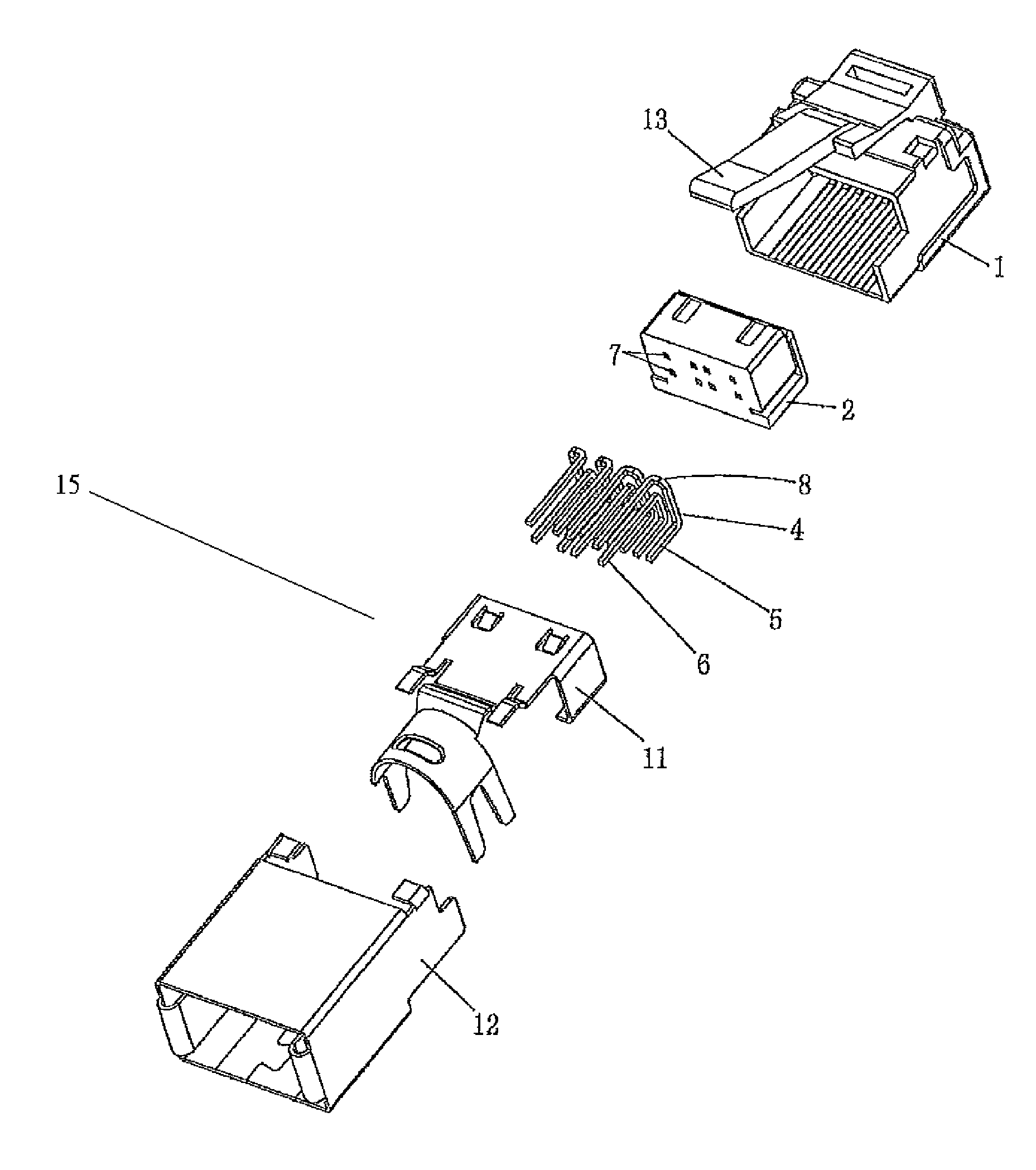
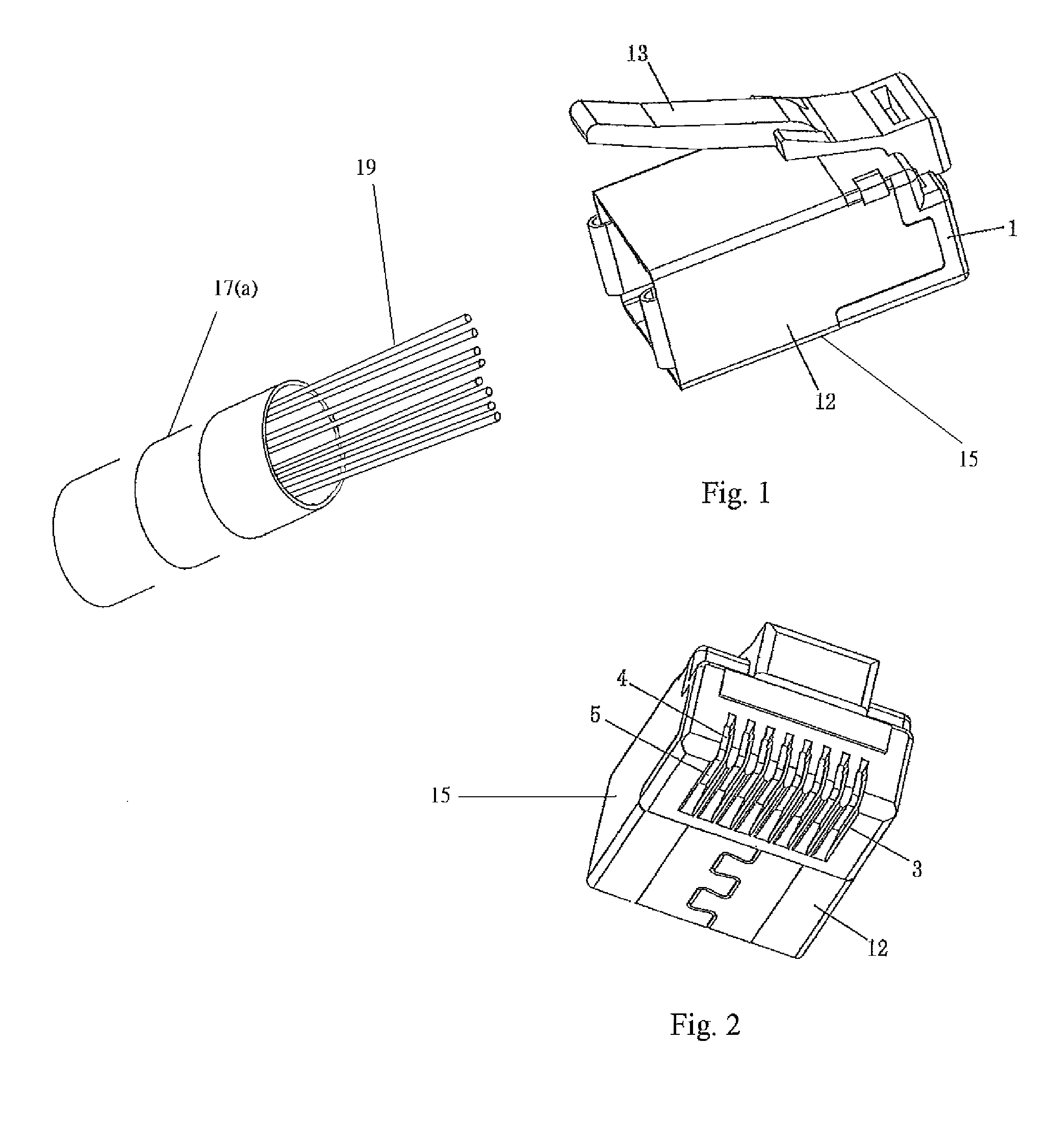
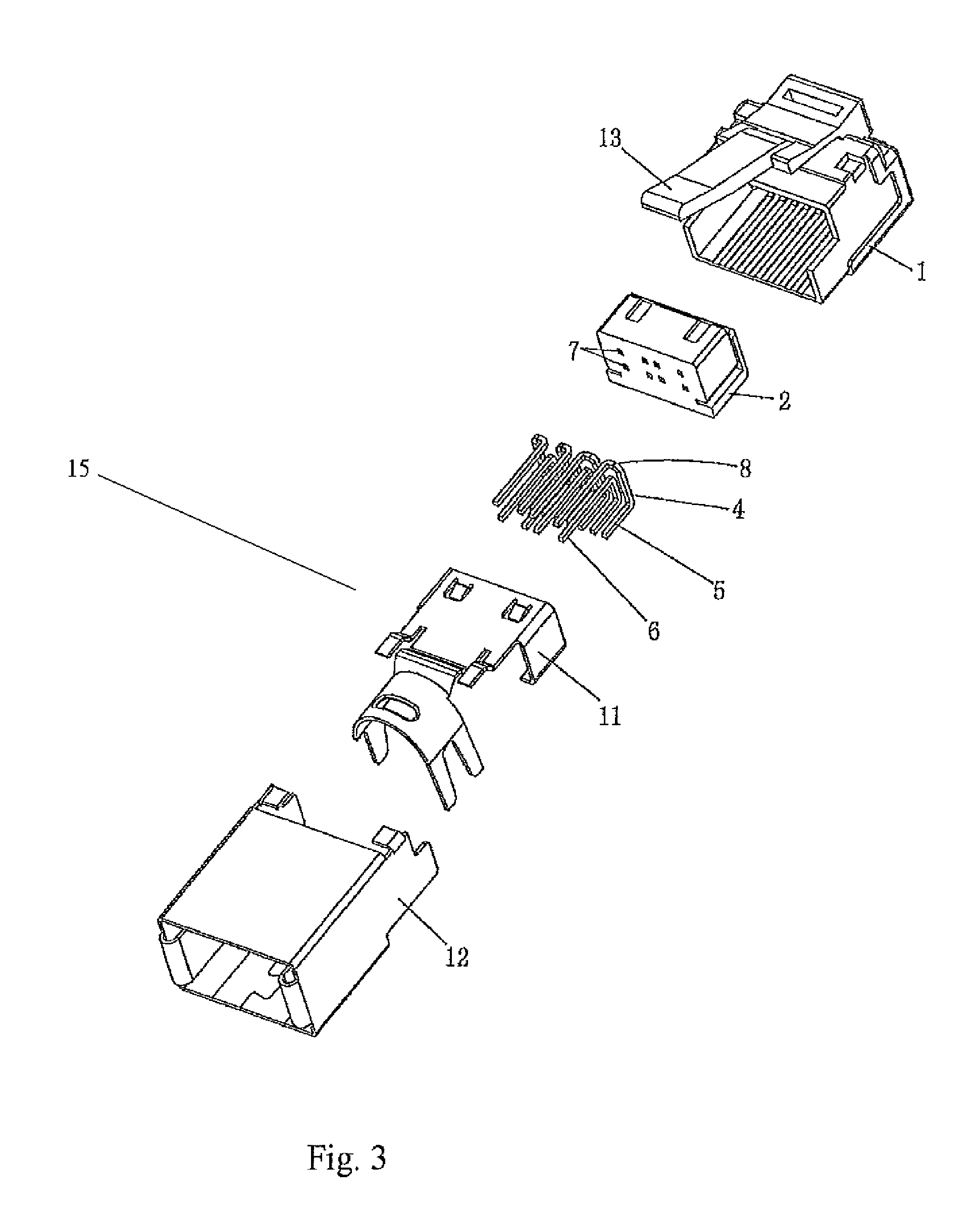
[0055]The first preferred embodiment of the network line plug of the present invention is shown in FIGS. 1˜11, wherein it comprises a short-head main body 1 and a rubber core 2; eight slots 3 are arranged in parallel onto the lower surface of said short-head main body 1, and used for insertion of the electrical contact within the female socket; said rubber core 2 is fixed into the short-head main body 1.

[0056]The present invention also comprises eight welded terminals 4, which are aligned separately with eight core wires 19 of a network cable 17; said welded terminals 4 are inserted into the rubber core 2; the first ends of the welded terminals 4 are electrical contact portions 5, which are arranged in a line and used for electrical connection between the welded terminals 4 and electrical contacts within the female socket; the second ends of the welded terminals 4 are welding portions 6, which are used to weld separately eight core wires 19 of the network line ...

embodiment 2

Preferred Embodiment 2

[0069]The second preferred embodiment of the network line plug of the present invention is shown in FIGS. 12˜17, wherein the network line plugs of this preferred embodiment and previous one are used in pair, with the same structure and technical package; the difference with the first preferred embodiment lies in that: the welding portions 6 of said welded terminals 4 are arranged in a different way; in this preferred embodiment, the welding portions 6 of welded terminals 4 for connection with any pair pf core wires 19 of the network cable 17 (which are intersected when wiring as per the network link protocol) are arranged vertically in alignment with the welding portions 6 of welded terminals 4 in the first preferred embodiment.

embodiment 3

Preferred Embodiment 3

[0070]The network line plug assembly of the present invention is implemented as shown in FIGS. 1˜17.

[0071]The network line plug assembly comprises of a network line plug implemented in the first preferred embodiment and a network line plug in the second preferred embodiment; two network line plugs are separately connected with the first and second ends of the network cable 17, of which the network line plug connected with the first end of the network cable 17(a) is a primary plug 15, and that connected with the second end of the network cable 17(b) is a secondary plug 16.

[0072]The welding portions 6 of two welded terminals 4 in the primary plug 15 for connection with any pair of core wires 19 of the network cable 17 (which are intersected when wiring as per the network link protocol) are arranged vertically in alignment with the welding portions 6 of two welded terminals 4 in the secondary plug.

[0073]The welding portions 6 of welded terminals 4 in the primary p...


PUM


Abstract

A network line plug and network line, and more particularly to a network line plug, network line plug assembly and network line; the network line plug of the present invention comprises of a short-head main body, rubber core and eight welded terminals; the rubber core is fixed into the short-head main body; said welded terminals are inserted into the rubber core; the first and second ends of said welded terminal are an electrical contact portion and welding portion, respectively; the welding portions of the welded terminal penetrate selectively the through-holes of the rubber core; the welding portions of two welded terminals corresponding to the same core pair are arranged adjacent to one another.

Description

BACKGROUND OF INVENTION[0001]1. Field of the Invention[0002]The present invention relates generally to the technology field of a network line plug and network line, and more particularly to a network line plug, plug assembly and network line.[0003]2. Description of Related Art[0004]The currently available network line plug is of a puncture structure, which comprises a main body, laying rubber plug, threading rubber plug, internal metal casing and external metal casing; eight core wires of the network cable penetrate separately through-hole on the threading rubber plug, which allows to position and assign these core wires onto the connecting location; the front end of the core wire is inserted into the groove on the laying rubber plug, which is used to fix these eight core wires and arrange them in a line; the main body is provided with eight slots, wherein a contact chip is inserted; when the network line plug is installed, the contact chip is pressed into the main body by a fixture...

Claims


Application Information

Patent Timeline
Patent Type & Authority Patents(United States)
IPC IPC(8): H01R4/50H01R13/625
CPCH01R4/023H01R9/03H01R13/5025H01R24/64H01R2107/00Y10S439/941
Inventor HSU, CHING-JEN
Owner YONGTAI ELECTRONICS DONGGUAN
Learn More