
Method and device for controlling motion of an industrial robot with a position switch

a technology of position switch and industrial robot, which is applied in the field of industrial robots, can solve the problems of affecting the working efficiency of the robot, affecting the operation of the robot, and requiring maintenance, and achieves the effects of reducing the working area of the robot, and reducing the workload of the robo

Active Publication Date: 2011-10-11
ABB (SCHWEIZ) AG
View PDF73 Cites 12 Cited by
  • Summary
  • Abstract
  • Description
  • Claims
  • Application Information

AI Technical Summary

Benefits of technology

[0023]An improved position switch according to an embodiment of the invention provides a method and device to limit the working area of a robot by software control. The software control is provided by using a position switch including at least one model based evaluator to evaluate a measured position and compare that to a reference position. The position is also assigned a trust value. Traditionally robots are developed with the option to use adjustable mechanical stops or cams and limit switches to carry out the function of a position switch on different axes of a robot arm. The mechanical elements, the stops, electro-mechanical limit switches or cams require space and machining on robot arm, which in return is costly and the arm is heavier.
[0024]By utilizing software control it is possible to make robot arm more compact, light and cost efficient. When a cam or other mechanical stop is not required on a part of the robot arm, that part will not require: extra space on the casting; costly machining to machine the cam etc out of the extra casting shape; a heavier structure. The benefits are multiplied somewhat because less material is needed on rotating parts, thus reducing load on the robot during operation. In addition no limit switches need to be adjusted, replaced or repaired. Maintenance required during total product life is reduced in terms of requirement both for repair and replacement.
[0025]Another advantage of the improved position switch is that re-configuring of the robot for other tasks is simplified. The present invention provides a more efficient way to re-configure motion limits and define a robot safe space. A programmed work envelope does no longer have to be the same as a total theoretical work envelope for the robot. It is no longer necessary for an engineer or technician to stop a robot in order to manually adjust limit switches or stop pieces on an arm or fixed part of the robot. In addition, the robot may be used to carry out one or more tasks in close cooperation with human operators in a safe manner according to industrial safety standards because of the improved limitation of the robot active working area provided by the improved position switch. Another advantage of the improved position switch is that logical combinations of axis limits for different axes of the robot may be quickly and simply set or re-set. In addition, the improved position switch may provide robot arm position information to a control unit during a time in which the robot is at a standstill, and so maintaining safety and synchronisation of the different axes of the robot arm.

Problems solved by technology

Generally speaking, mechanical position switches are expensive, require maintenance, and need additional cables between machine and controller.
This type of supervision may however, trigger a stop because the control error exceeds the threshold due to some unforeseen robot movement.
Amongst other things, a difference between reference and measured positions, which may be seen as a type of servo control error, may increase due to dynamic effects such as servo lag and transients during acceleration.

Method used


Image

  • Method and device for controlling motion of an industrial robot with a position switch
  • Method and device for controlling motion of an industrial robot with a position switch
  • Method and device for controlling motion of an industrial robot with a position switch

Examples


Embodiment Construction

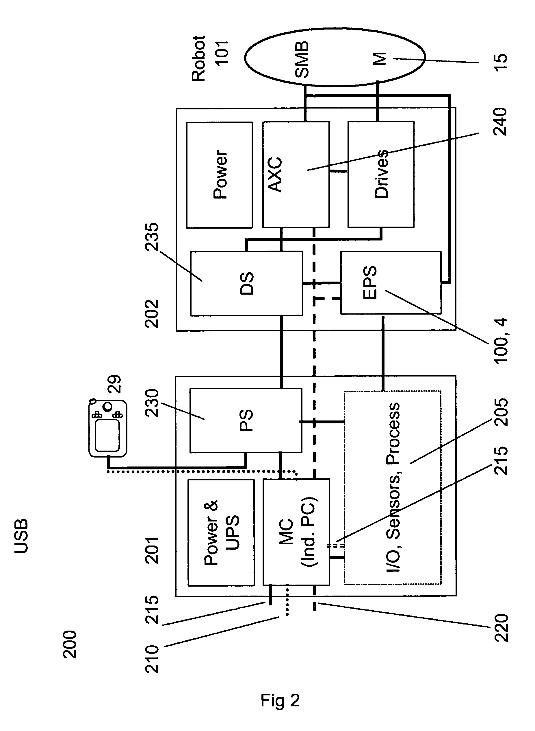
[0040]An improved position switch according to an embodiment of the invention provides a programmable electronic position switch in the form of an electronic computer with at least one CPU and associated memory, and a model-based evaluator, MBV. The MBV is run in the CPU which is connected to a communication channel where references that are sent to a servo controller can be “read”, and also connected to a measurement channel where motor positions are readable. The MBV has at least one model for each servo axis and at least one model for each gearbox of the machine under supervision.

[0041]FIG. 1 shows an improved position switch 100 in the form of a programmable electronic position switch according to an embodiment of the invention. It shows a Model Based Evaluator (MBV) 4, a Voting Unit 30 and a Programmable Safety Function 40. The Programmable Safety Function may be configured by a safety program 38 or by configuration. The MBV is supplied with a position reference 1 and a positio...


PUM


Abstract

A method for controlling a multi-axis industrial robot or manipulator arranged with a robot control unit. The robot or the control unit includes at least one first computer running a servo controller. A motion limit is configured for at least one axis of the robot arm. A reference signal for a robot position is sent to a robot controller together with a measurement of a position of the robot arm. The reference position is processed and the measured position and the processed reference position are then compared in an evaluator for the purpose of limiting the motion of an arm of the robot.

Description

CROSS-REFERENCE TO RELATED APPLICATIONS[0001]This application claims priority to U.S. provisional patent application 60 / 736,835 filed 16 Nov. 2005 and is the national phase under 35 U.S.C. §371 of PCT / EP2006 / 068443 filed 14 Nov. 2006.TECHNICAL FIELD[0002]The present invention concerns an industrial robot and relates to a method, a device and a system for limiting extent of motion in one or more axes of the robot.BACKGROUND ART[0003]Programmable, servo-controlled machines like industrial robots are often equipped with position switches for limiting their workspace or allow interlocking of the machine with other moving equipment. These position switches often use a machined cam to define the switching positions. In particular positions switches are often used in applications where occupational safety regulations have to be followed.[0004]U.S. Pat. No. 5,558,196 to Nehei et al entitled Device for detecting limits of rotational motion in a robot (Fanuc) a device for detecting the limits...

Claims


Application Information

Patent Timeline
Patent Type & Authority Patents(United States)
IPC IPC(8): G05B15/00G05B19/00
CPCB25J9/1674
Inventor HELLBERG, MAGNUSTHULIN, MATSFORS, MICHAELMIKAELSSON, PIERRETHORS, TOMMYKOCK, SONKEBEHNISCH, KEVINERIKSSON, PETERBREDAHL, JANTORESSON, BO
Owner ABB (SCHWEIZ) AG
Learn More