Temporal magnetic resonance imaging

Active Publication Date: 2011-10-11
FONAR
View PDF90 Cites 28 Cited by
  • Summary
  • Abstract
  • Description
  • Claims
  • Application Information

AI Technical Summary

Benefits of technology

[0020]As further discussed below, it is relatively simple to register the data sets at a particular, readily identifiable anatomical structure. If the data sets are registered at a particular anatomical structure, the comparison image set will accurately reflect meaningful anatomical changes in the vicinity of that anatomical structure.

Problems solved by technology

Moreover, MRI allows visualization of tissues which are difficult or impossible to depict using other techniques.
However, magnetic resonance imaging procedures have suffered from significant limitations.
None of these systems have been widely adopted.
Even with the capabilities achievable in MRI imaging, it is not always easy to spot disease states or changes in the patient's condition.

Method used


Image

  • Temporal magnetic resonance imaging
  • Temporal magnetic resonance imaging
  • Temporal magnetic resonance imaging

Examples


Embodiment Construction

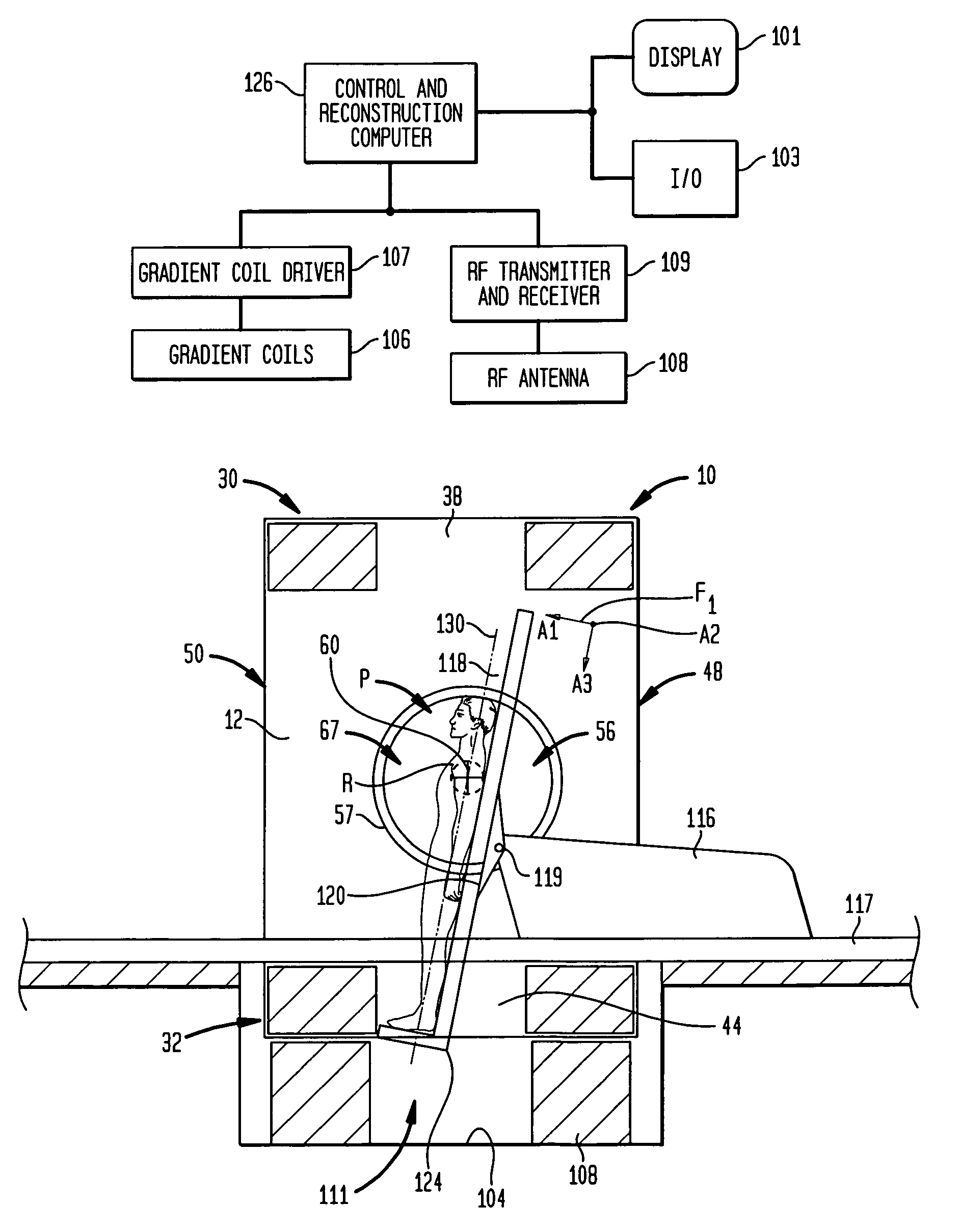
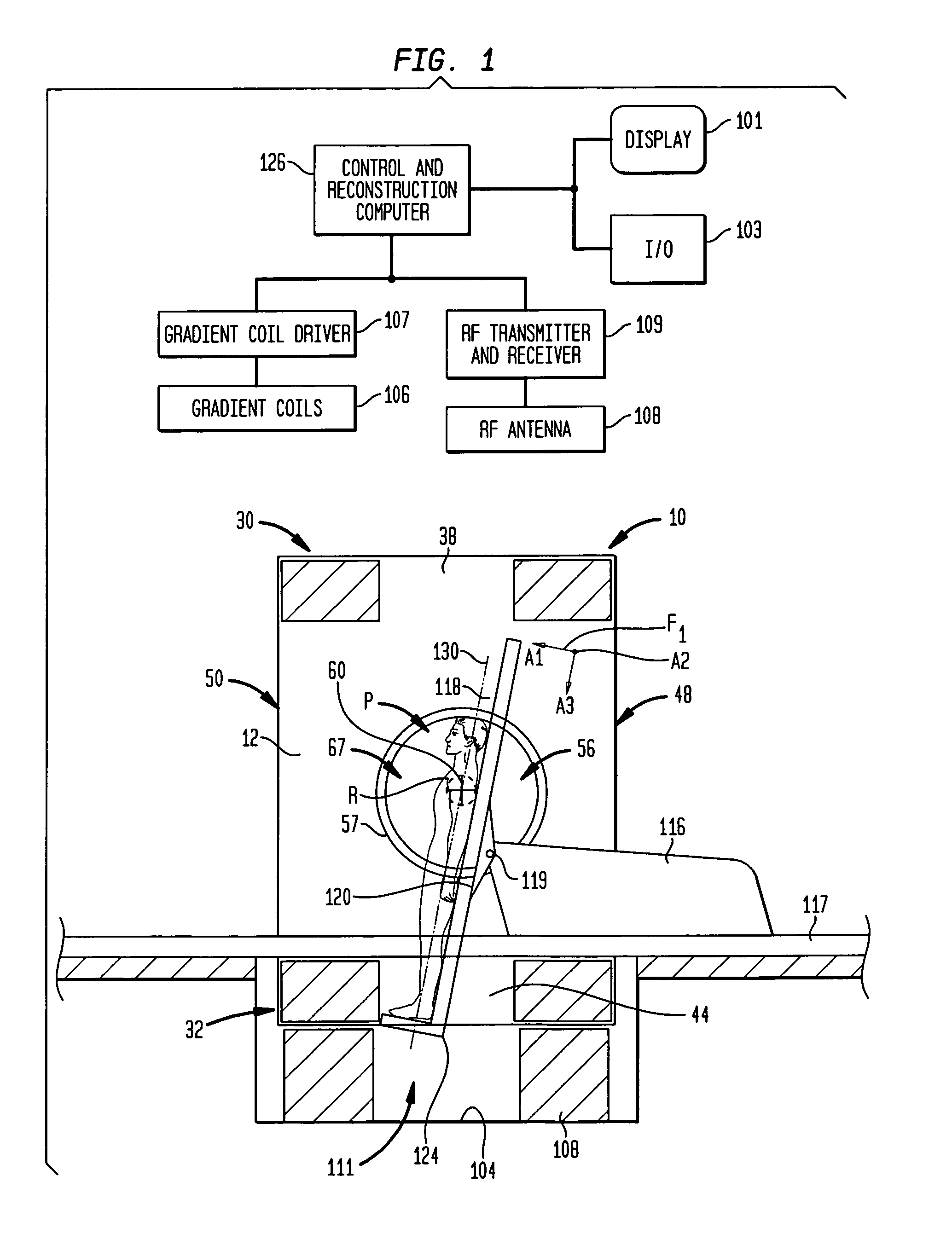
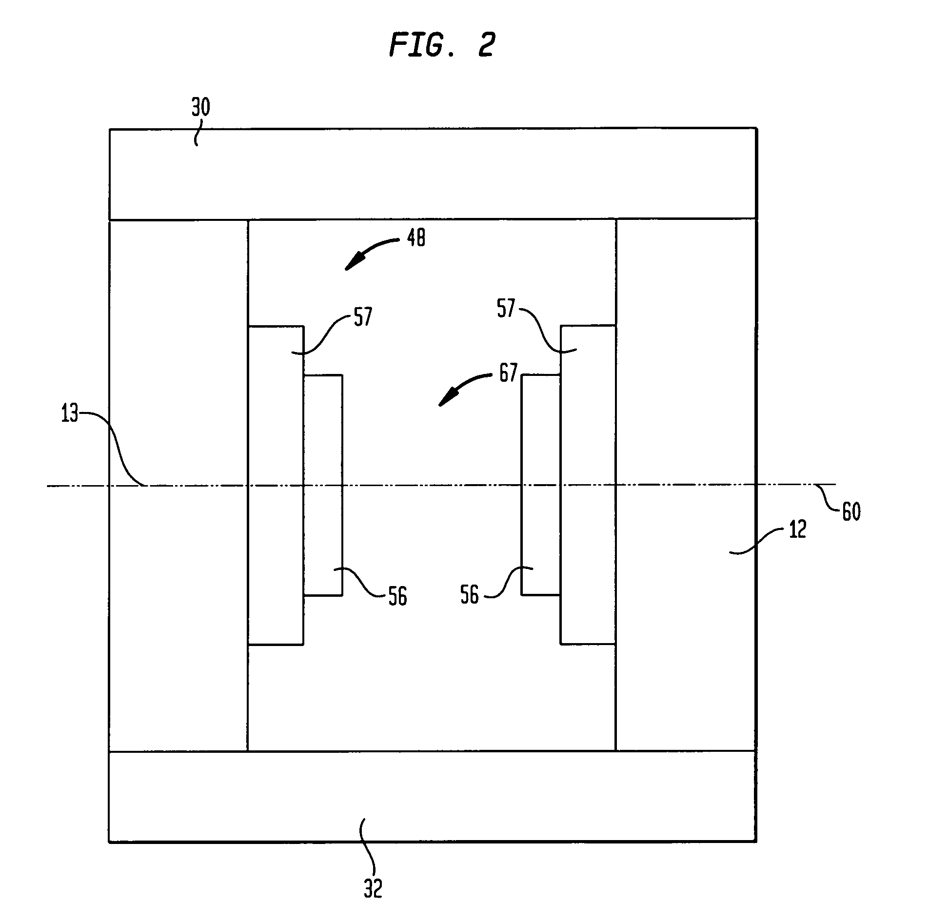
[0026]Although many different types of magnetic resonance imaging apparatus can be used in accordance with the present invention, one apparatus used in one embodiment of the present invention is depicted in FIG. 1. This apparatus includes a ferromagnetic frame 10. As described in greater detail in the '946 application, the frame 10 is generally in the form of a hollow rectangular solid and includes a top flux return member 30 defining the top wall of the frame, a bottom flux return member 32 defining the bottom wall of the frame and a pair of generally vertical side walls 12 and 13 (FIG. 2) defining the sides of the frame, one such side wall 12 being visible in FIG. 1. The frame has large patient entry openings 48 and 50 (FIG. 1) at front and back sides of the frame, i.e., the vertical sides which are not occupied by side wall 12 and the opposite side wall. The top flux return member 30 defines opening 38 in the top wall of the frame, whereas the bottom flux return member 32 defines...


PUM


Abstract

A patient is subjected to magnetic resonance imaging at substantial intervals such as weeks, months or years, or after an interval sufficient for a therapeutic regimen to affect the anatomy, and the data acquired at different times is compared to show changes in the anatomy with time or due to the effects of the therapeutic regimen. Individual data elements or larger groups of plural data elements representing particular locations a set of image data acquired at one time can be automatically compared with data elements associated with the same locations in another set of image data acquired at another time to yield a set of comparison data.

Description

CROSS-REFERENCE TO RELATED APPLICATIONS[0001]The present application claims benefit of U.S. Provisional Patent Application Ser. No. 60 / 373,789, filed Apr. 19, 2002, the entire disclosure of which is hereby incorporated by reference herein.BACKGROUND OF THE INVENTION[0002]The present invention relates to imaging techniques and apparatus for performing such techniques.[0003]In magnetic resonance imaging (“MRI”), a strong, uniform magnetic field is applied to the region of the patient to be imaged. Radio frequency (“RF”) energy is applied to this region of the patient by a transmitter and antenna. The RF energy excites atomic nuclei within the patient's tissues. The excited nuclei spin at a rate dependent upon the magnetic field. As they spin, they emit faint RF signals, referred to herein as magnetic resonance signals. By applying small magnetic field gradients so that the magnitude of the magnetic field varies with location within the patient's body, the magnetic resonance phenomenon...

Claims


Application Information

Patent Timeline
IPC IPC(8): A61B5/05G01V3/00
CPCA61B5/0555G01R33/543G01R33/546A61B5/7425G01R33/383G01R33/5673A61B2576/00G16H30/40A61B5/055
Inventor DAMADIAN, RAYMOND V.GIAMBALVO, ANTHONY J.
Owner FONAR
Why Eureka
Try Eureka