
Apparatus and method for manufacturing an organic electroluminescence display

a manufacturing apparatus and electroluminescence display technology, applied in the field of manufacturing apparatus for organic electroluminescence display and organic electroluminescence display, can solve the problems of large-scale production of such a display using organic electroluminescence elements, difficult mass production, and inability to meet the requirements of organic electroluminescence elements, etc., to shorten the cycle time of the process, and suppress the consumption of organic materials.

Inactive Publication Date: 2011-10-11
SONY CORP
View PDF40 Cites 0 Cited by
  • Summary
  • Abstract
  • Description
  • Claims
  • Application Information

AI Technical Summary

Benefits of technology

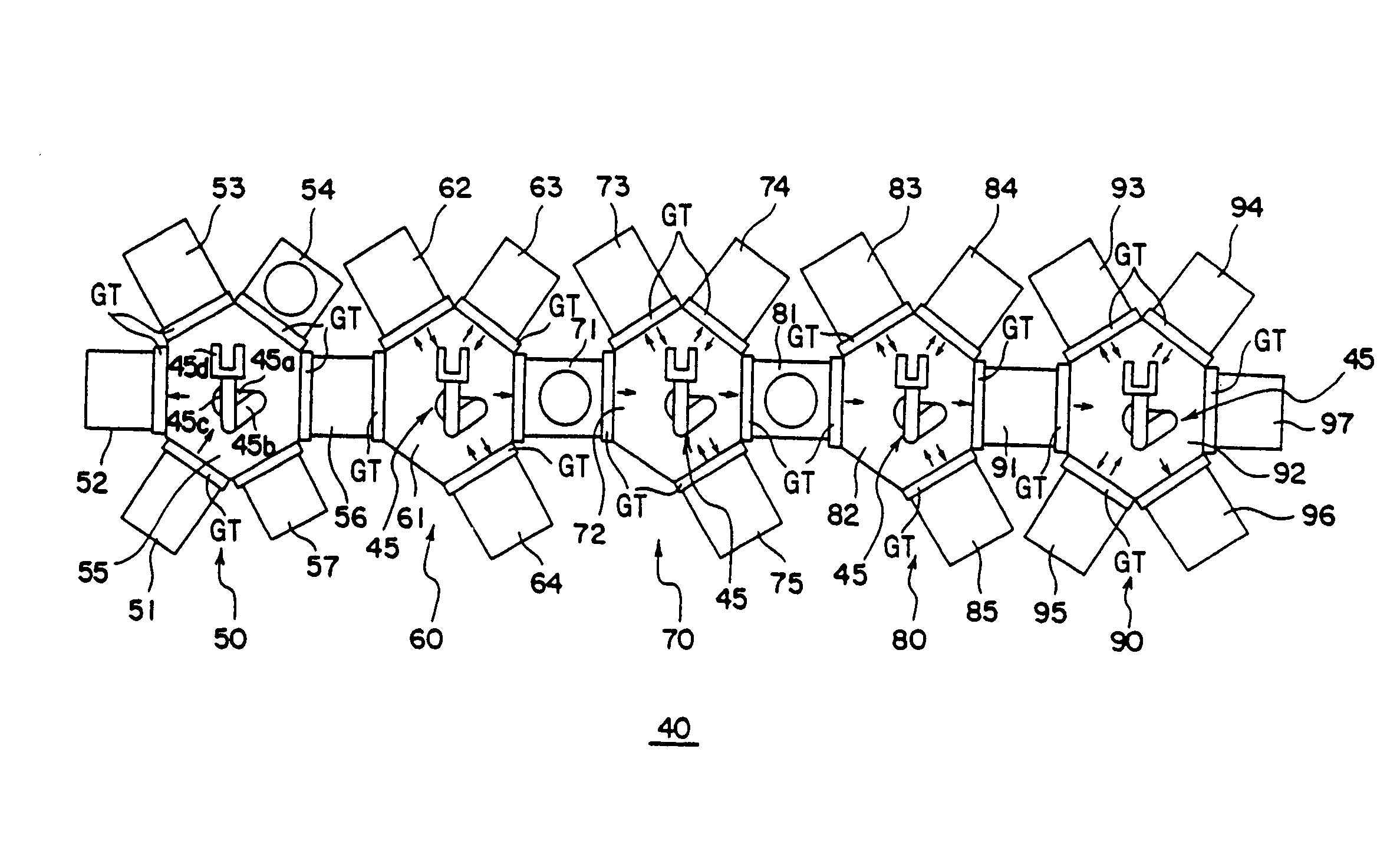
The present invention provides an apparatus and method for manufacturing an organic electroluminescence display that can shorten the cycle time of forming an organic layer and suppress wasteful consumption of organic materials. The method involves aligning a mask with the substrate, attaching the mask and substrate, and sequentially forming layers of organic materials on the substrate in multiple vacuum processing chambers. The apparatus includes an alignment mechanism, a number of vacuum processing chambers, and a transferring mechanism for sequentially transferring the mask and substrate among the chambers. This method and apparatus can eliminate the need for alignment between the mask and substrate and save time during the manufacturing process.

Problems solved by technology

However, when forming an organic layer having a number of organic material layers in the same processing chamber, as described above, there are disadvantages in that a cycle time of the process for forming the organic layer can become extremely long.
Thus, mass production of such a display using organic electroluminescence elements can be difficult.
A relatively long time is needed until reaching the desired temperature and a relatively long time is needed until an evaporation rate of a vapor deposition source becomes stable.
As a result, it takes an extremely long time to form an organic layer.
Thus, wasteful consumption of materials is hard to avoid.
The organic materials used for an organic electroluminescence element are very costly, so the production cost of the organic layer swells and, as a result, the mass production of a display using organic electroluminescence elements becomes difficult.
As a result, it is very difficult to sufficiently shorten the cycle time of the process for forming an organic layer.
Further, during the alignment work, the vapor deposition materials can be wasted.

Method used


Image

  • Apparatus and method for manufacturing an organic electroluminescence display
  • Apparatus and method for manufacturing an organic electroluminescence display
  • Apparatus and method for manufacturing an organic electroluminescence display

Examples


Embodiment Construction

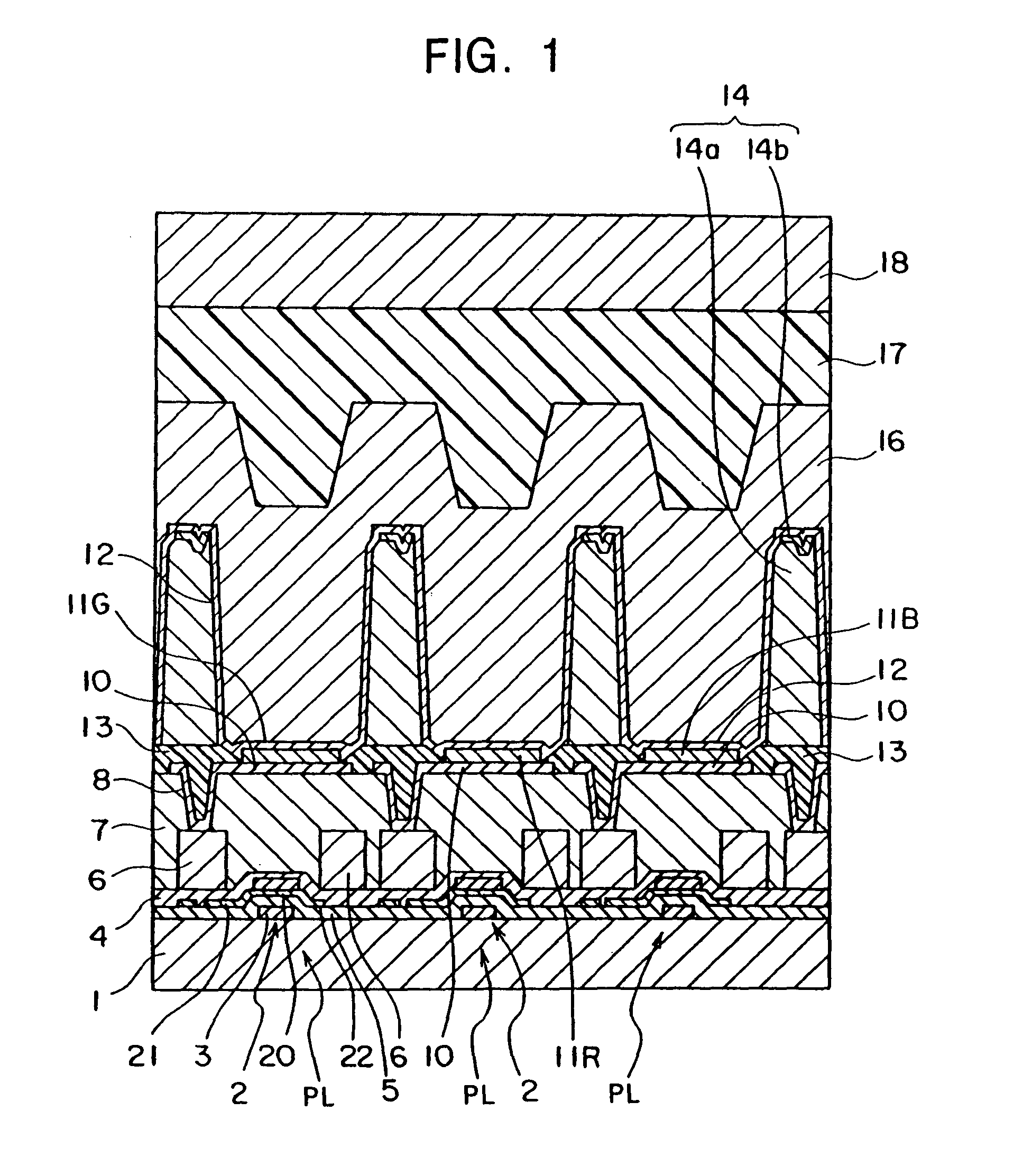
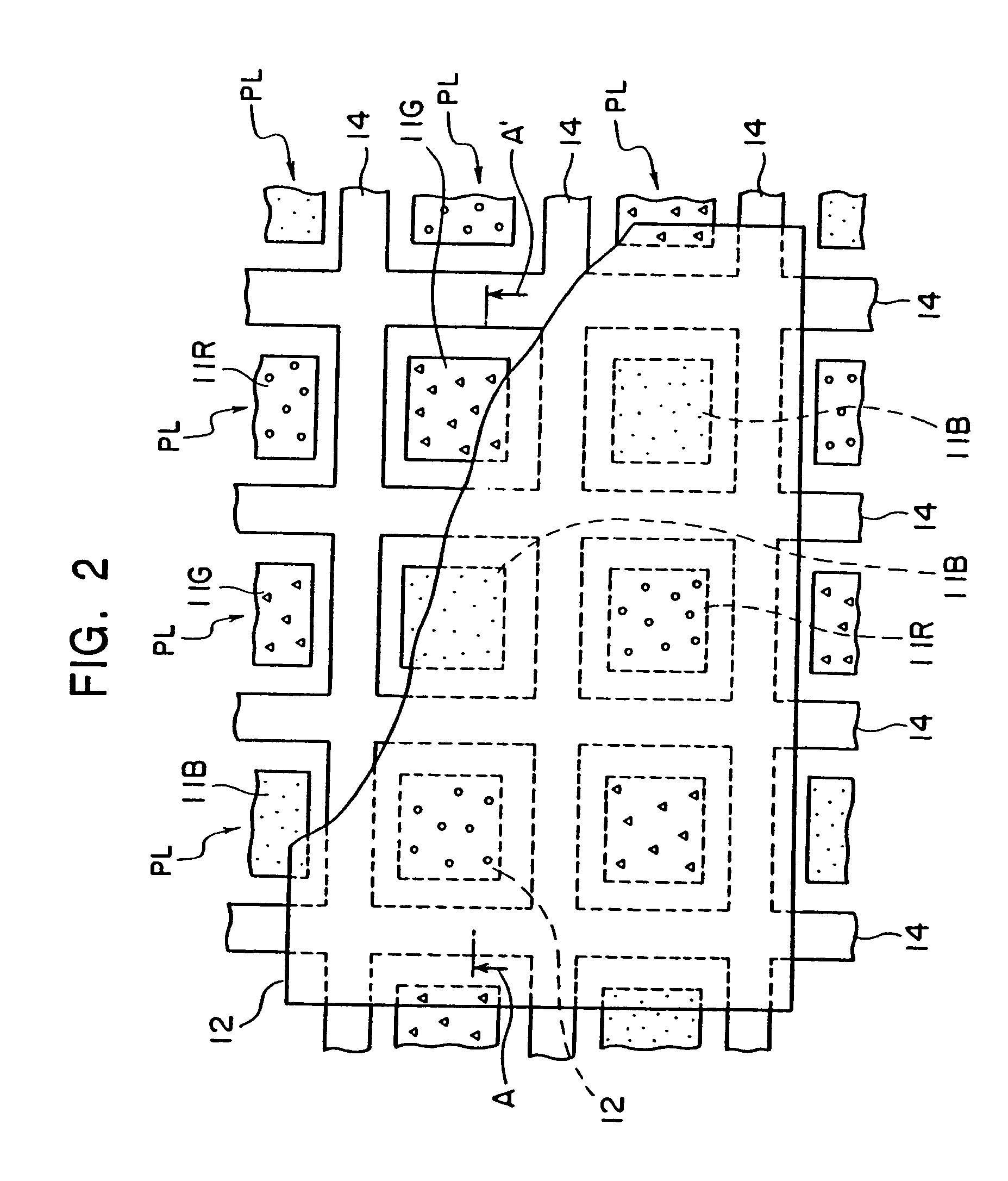
[0043]FIG. 1 and FIG. 2 are views of an example of the organic electroluminescence display to which the present invention is applied. Specifically, FIG. 1 is a cross-sectional view of a portion of the general configuration of the display area of the organic electroluminescence display, while FIG. 2 is a plan view of a portion of the general configuration of the display area of the organic electroluminescence display. Note that FIG. 1 is a cross-sectional view along the direction of the line A-A′ in FIG. 2. Further, the organic electroluminescence display shown in FIG. 1 and FIG. 2 is an active matrix type of color display.

[0044]The display in FIG. 1 has a substrate 1, a number of thin film transistors 2, anode electrodes 10 formed on the transistors 2 via an interlayer insulating layer 7, and organic layers 11G, 11R, and 11B which are formed on the anode electrodes 10 and emit colors of green (G), red (R), and blue (B) respectively. The display also has a cathode electrode 12 formed...


PUM

PropertyMeasurementUnit
thicknessaaaaaaaaaa
thicknessaaaaaaaaaa
thicknessaaaaaaaaaa

Abstract

An apparatus for manufacturing an organic electroluminescence display having an alignment chamber for aligning a mask having openings corresponding to a predetermined pattern with a substrate on which a first electrode layer is formed and detachably attaching the mask and the substrate. The apparatus further including a number of vacuum processing chambers for sequentially forming a number of organic material layers on the substrate attached with the mask. The apparatus also including a transfer robot for transferring the attached mask and substrate to one of the number of vacuum processing chambers and sequentially transferring it between the number of the vacuum processing chambers.

Description

CROSS REFERENCE TO RELATED APPLICATIONS[0001]This patent application is a divisional of U.S. application Ser. No. 10 / 153,453, filed on May 21, 2002, the disclosure of which is herein incorporated by reference.BACKGROUND OF THE INVENTION[0002]The present invention relates to both a manufacturing apparatus for an organic electroluminescence display and a method of manufacturing an organic electroluminescence display.[0003]An organic electroluminescence element is structured by an organic layer including an organic material sandwiched between electrodes made of an anode and a cathode. It is known that when voltage is applied across these electrodes, electrons and holes are injected from the cathode and anode into the organic layer of the organic electroluminescence element. These electrons and holes recombine to emit light.[0004]In such an organic electroluminescence element, a luminescence of, for example, several hundreds to several tens of thousands of cd / m2 is obtained with a drivi...

Claims


Application Information

Patent Timeline
Patent Type & Authority Patents(United States)
IPC IPC(8): C23C16/00C23C16/04H05B33/10C23C14/02C23C14/04C23C14/12C23C14/56G09F9/00G09F9/30H01L27/12H05B33/12H05B33/22H10K99/00
CPCC23C14/022C23C14/042C23C14/12C23C14/568H01L27/12H01L27/3211H01L51/56H01L27/3244H01L27/3295H01L51/0008H10K59/35H10K59/122H10K59/12H10K71/16H05B33/10H10K71/00
Inventor MORI, TAKAOYAMAGUCHI, MASARUKAMIYAMA, ISAO
Owner SONY CORP
Learn More