
Droplet ejection apparatus and droplet ejection method

a technology of droplet ejection and droplet, which is applied in the direction of printing, other printing apparatus, etc., can solve the problems of increasing the amount of treatment liquid applied, increasing the cost of the apparatus, and increasing the size of the apparatus, so as to reduce the density non-uniformities in the image

Inactive Publication Date: 2011-10-04
FUJIFILM CORP
View PDF2 Cites 3 Cited by
  • Summary
  • Abstract
  • Description
  • Claims
  • Application Information

AI Technical Summary

Benefits of technology

[0008]The present invention has been contrived in view of the foregoing, an object thereof being to provide a droplet ejection apparatus and a droplet ejection method whereby, even in cases where there is variation in the volume of treatment liquid deposited onto a medium, density non-uniformities in an image caused by variation in the aggregation of ink on the medium can be reduced, while restricting increase in the size of the apparatus.

Problems solved by technology

Furthermore, since the treatment liquid proceeds to permeate into the medium when the conveyance of the medium is halted, then there is a tendency for the amount of treatment liquid applied to increase.
If there are variations in the application of the treatment liquid, then variations in aggregation occur when the ink aggregates, and ultimately, density non-uniformities arise in the image.
By this means, even if the medium is halted at the ink droplet ejection position, it is possible to apply treatment liquid by conveying the medium in a continuous fashion, at the treatment liquid application position, but on the other hand problems arise in that in order to provide space for the buffer, the apparatus becomes large in size and costs increase.

Method used


Image

  • Droplet ejection apparatus and droplet ejection method
  • Droplet ejection apparatus and droplet ejection method
  • Droplet ejection apparatus and droplet ejection method

Examples


first embodiment

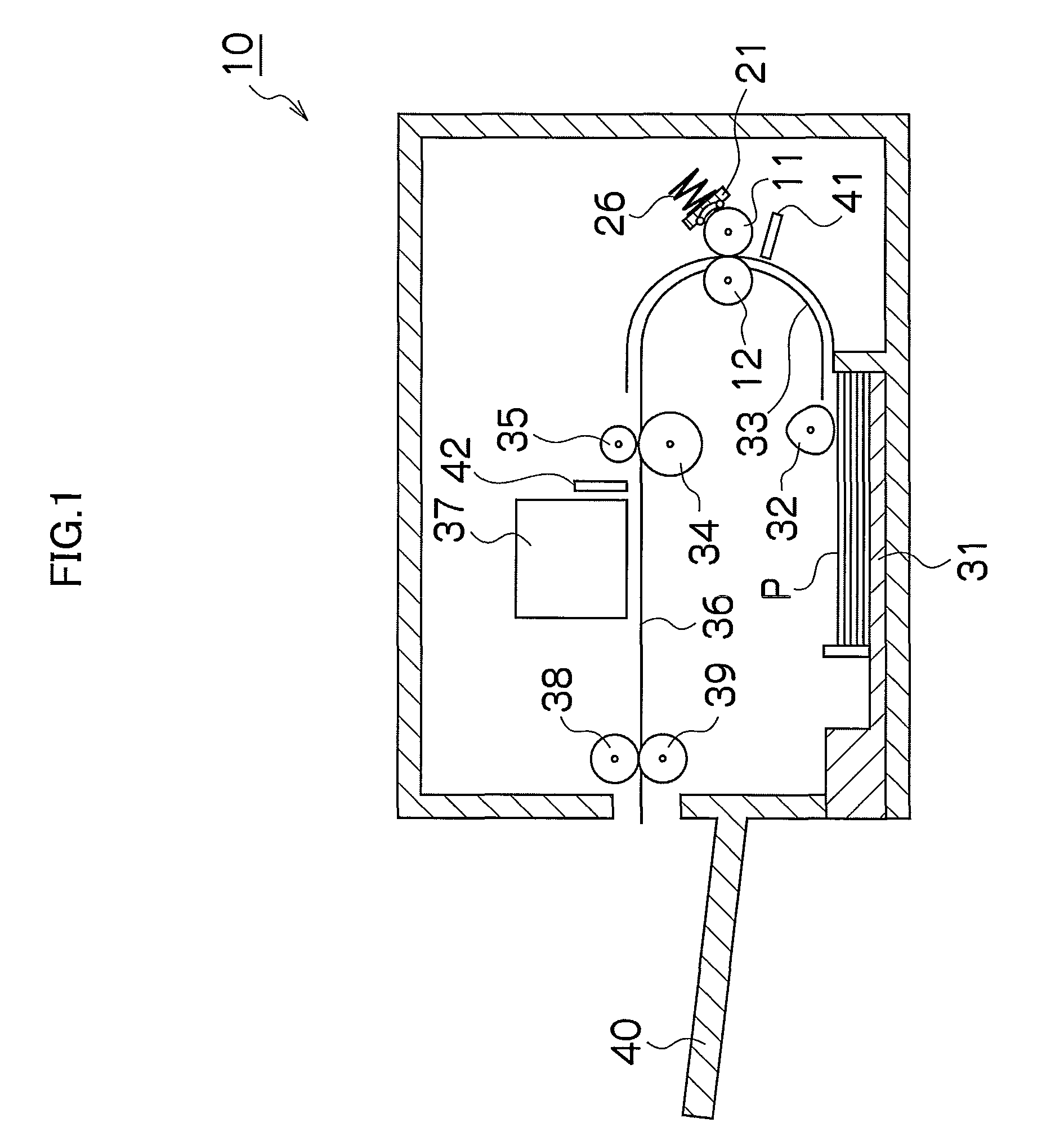
[0054]FIG. 1 is a general schematic drawing of an image forming apparatus 10 according to a first embodiment which employs a droplet ejection apparatus relating to an embodiment of the present invention.

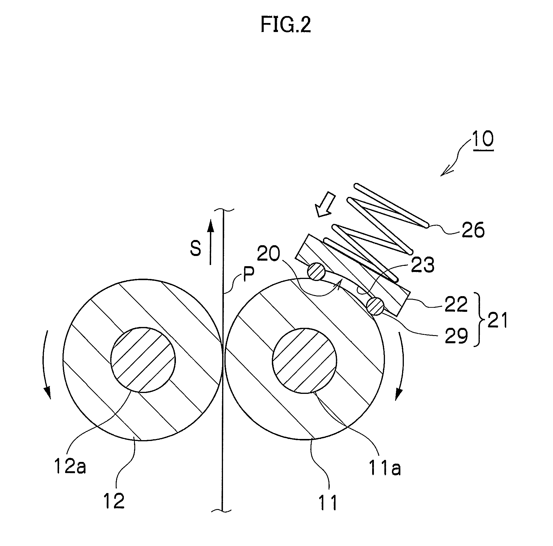
[0055]In FIG. 1, a plurality of recording media P (hereinafter, called “media”) are loaded into a paper supply unit 31. A feed roller 32 picks up the media P which are loaded in the paper supply unit 31, one sheet at a time, and conveys same to a conveyance path 33. An application roller 11 which applies a treatment liquid to the medium P and a back-up roller 12 which opposes the application roller 11 and supports the medium P are provided in the conveyance path 33. The liquid holding member 21 is impelled toward the outer circumferential surface of the application roller 11 by the impelling force of an impelling member 26, such as a spring member, and forms a liquid holding space between itself and the outer circumferential surface of the application roller 11 by abutting against th...

second embodiment

[0091]In the present embodiment, a droplet ejection head having a plurality of nozzles (hereinafter, a “treatment liquid droplet ejection head”) is used as a treatment liquid deposition device which deposits treatment liquid onto the medium. Furthermore, in the present embodiment, density non-uniformities in the image caused by aggregation non-uniformities of the ink on the medium are corrected by correcting the ink droplet ejection volume in accordance with the overlapping surface area (extent of overlap) of the treatment liquid dots and ink dots formed on the medium.

[0092]FIG. 14 is a general schematic drawing of an image forming apparatus 100 according to a second embodiment which employs a droplet ejection apparatus relating to an embodiment of the present invention. The same reference numerals are assigned to constituent elements which are the same as the constituent elements of the image forming apparatus 10 of the first embodiment which is illustrated in FIG. 1, and details w...


PUM


Abstract

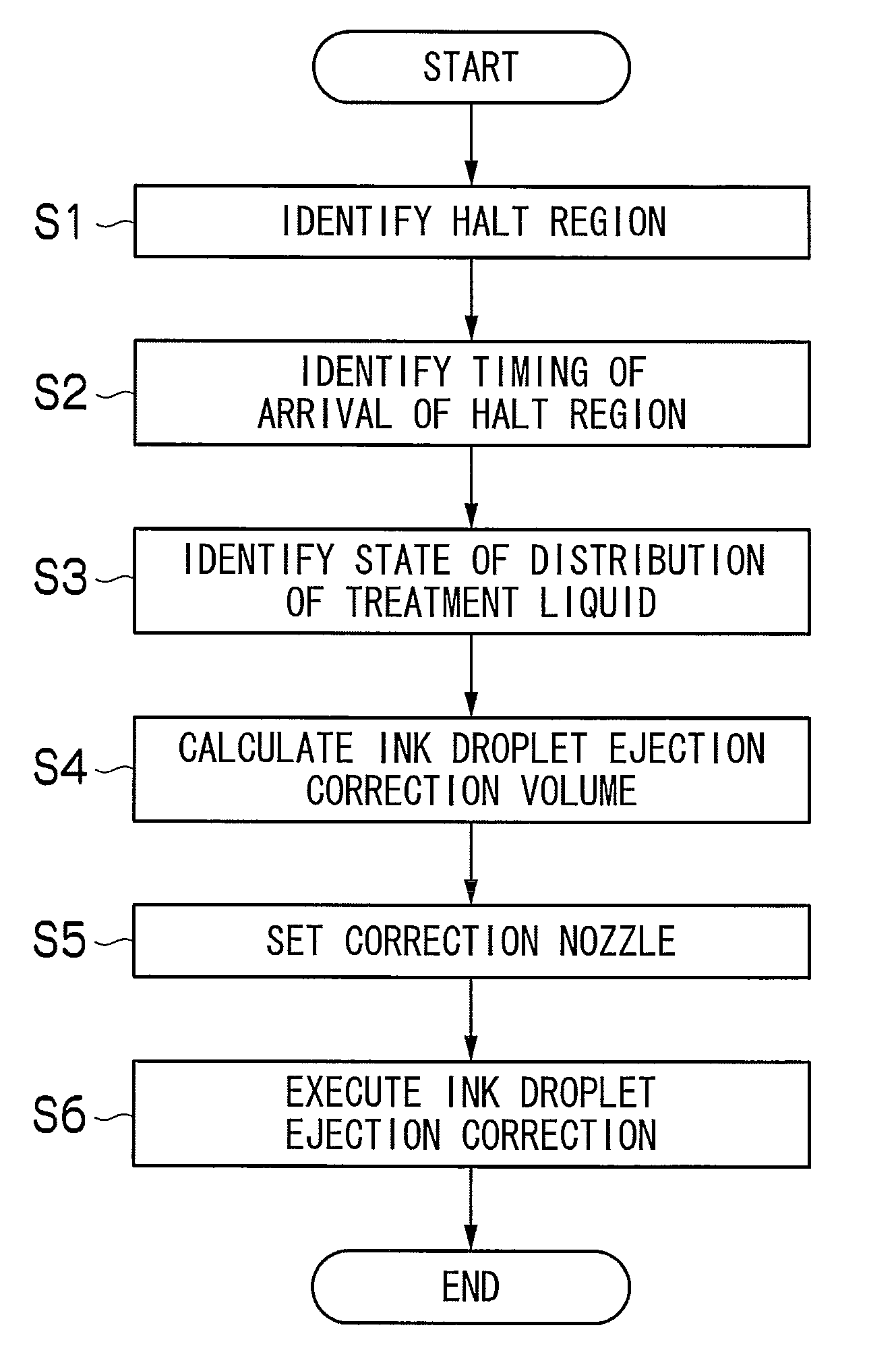
A droplet ejection apparatus includes: a treatment liquid deposition device which deposits treatment liquid aggregating ink onto a medium; an ink droplet ejection device which ejects droplets of ink onto the medium on which the treatment liquid has been deposited; and a droplet ejection correction device which corrects a droplet ejection volume of the ink droplet ejection device in accordance with distribution of the treatment liquid on the medium.

Description

BACKGROUND OF THE INVENTION[0001]1. Field of the Invention[0002]The present invention relates to a droplet ejection apparatus and a droplet ejection method whereby ink droplets are ejected onto a medium after depositing an ink aggregating treatment liquid onto the medium.[0003]2. Description of the Related Art[0004]Technology is known in which droplets of ink are ejected after depositing an ink aggregating treatment liquid onto a medium. For example, Japanese Patent Application Publication No. 2007-83180 discloses a small printer which applies a treatment liquid to a medium before the ejection of ink droplets, by using a round cylindrical application roller.[0005]In a small printer, generally, a so-called shuttle type of ink droplet ejection head is used, which moves back and forth reciprocally in the direction (main scanning direction) that is perpendicular to the medium conveyance direction, and therefore intermittent conveyance is carried out by repeating conveyance and halting o...

Claims


Application Information

Patent Timeline
Patent Type & Authority Patents(United States)
IPC IPC(8): B41J29/393
CPCB41J2/2114B41J11/0015B41J29/38
Inventor KUSUNOKI, NAOKI
Owner FUJIFILM CORP
Learn More