
Method for manufacturing electronic device, and electronic device

a technology of electronic devices and manufacturing methods, applied in the direction of semiconductor/solid-state device details, printed circuit non-printed electric components association, other domestic articles, etc., can solve the problems of further restricting the penetration of the substrate through the hole by the constituent material, and restricting the size of the substrate. , to achieve the effect of restricting the siz

Active Publication Date: 2017-11-28
DENSO CORP
View PDF20 Cites 0 Cited by
  • Summary
  • Abstract
  • Description
  • Claims
  • Application Information

AI Technical Summary

Benefits of technology

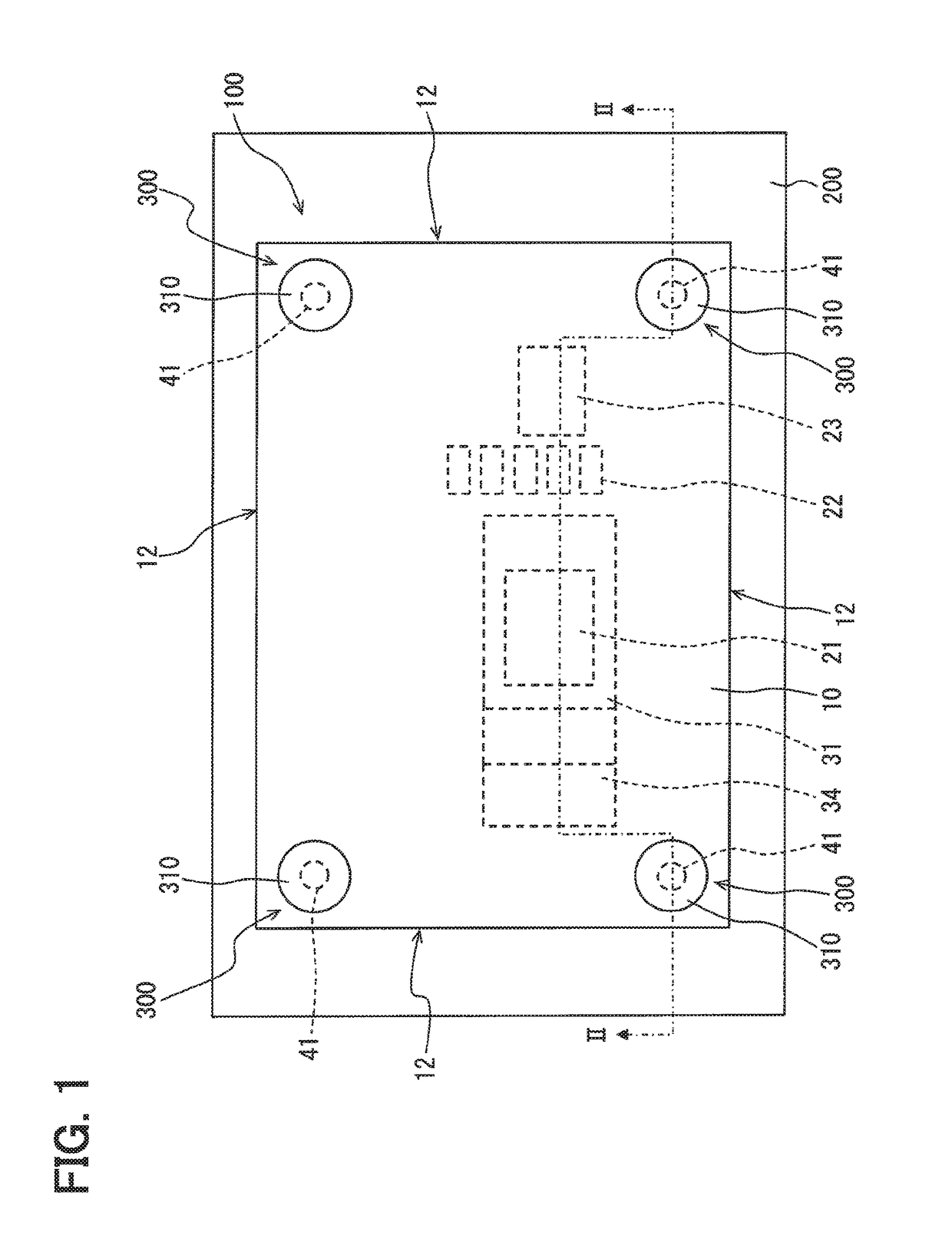
[0006]It is an object of the present disclosure to provide a method for manufacturing an electronic device by which an increase in size can be restricted. Another object of the present disclosure is to provide an electronic device that is compact in size.
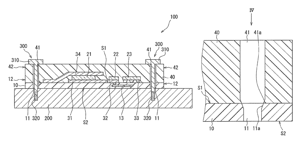
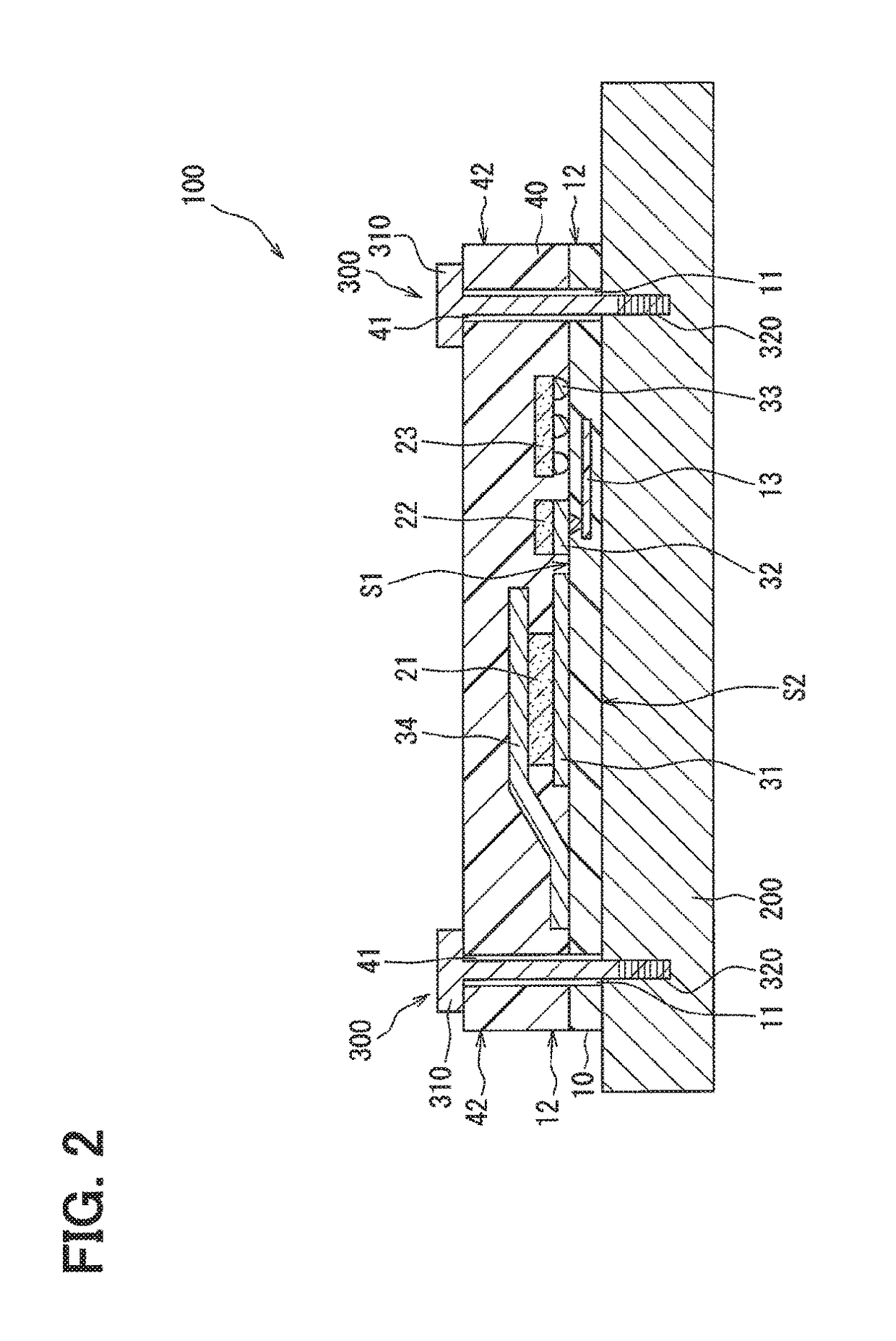
[0009]In addition, the substrate through hole is blocked by the pressing member in the method for manufacturing an electronic device described above, and thus penetration of the substrate through hole by the constituent material can be restricted. Furthermore, in the method for manufacturing an electronic device described above, the molding is performed in a state where the pressing member is pressed against the circuit board so that the circuit board is deformed, and thus penetration of the substrate through hole by the constituent material can be further restricted.

Problems solved by technology

In addition, the substrate through hole is blocked by the pressing member in the method for manufacturing an electronic device described above, and thus penetration of the substrate through hole by the constituent material can be restricted.
Furthermore, in the method for manufacturing an electronic device described above, the molding is performed in a state where the pressing member is pressed against the circuit board so that the circuit board is deformed, and thus penetration of the substrate through hole by the constituent material can be further restricted.

Method used


Image

  • Method for manufacturing electronic device, and electronic device
  • Method for manufacturing electronic device, and electronic device
  • Method for manufacturing electronic device, and electronic device

Examples


first modification example

[0109]An electronic device according to the first modification example has a circuit board 10a. In the circuit board 10a, conductive portions 14 are disposed on inner wall surfaces of through holes in the resin base material as illustrated in FIG. 17. In other words, the substrate through hole 11 is disposed between the conductive portions 14 in the circuit board 10a.

[0110]A metal such as copper constitutes this conductive portion 14 and the conductive portion 14 is equivalent to a conductive member. The conductive portion 14 is disposed in an annular shape over an entire circumference of the through hole in the resin base material and is also disposed on a part of the surface S1 and a part of the reverse surface S2. In other words, a region of the circuit board 10a that is surrounded by portions of the conductive portions 14 placed in the through holes in the resin base material is the substrate through hole 11. The inner wall surface means a surface that is exposed to the through...

second modification example

[0117]An electronic device according to the second modification example has a circuit board 10b. In the circuit board 10b, a conductive portion 141 is disposed on the inner wall surface of the through hole in the resin base material as illustrated in FIG. 21. This conductive portion 141 differs in shape from the conductive portion 14. The circuit board 10b is provided with the conductive inclined portion 14a and the resin inclined portion 11a as in the case of the circuit board 10a.

[0118]The conductive portion 141 is provided with a conductive flat portion 14b that is parallel to a thickness direction of the circuit board 10b. In the circuit board 10b, the conductive flat portion 14b is provided further on the reverse surface S2 side than the conductive inclined portion 14a. The conductive flat portion 14b is provided to be continuous with respect to the conductive inclined portion 14a via a portion along the thickness direction. A resin flat portion 11b, which is deformed when the...

third modification example

[0121]As illustrated in FIG. 22, an electronic device according to the third modification example has a circuit board 10c in which a dam portion 15 is disposed on a surface of the conductive portion 14. The dam portion 15 is provided in an annular shape on the conductive portion 14 and is sealed by the mold resin 40. The dam portion 15 is provided on the conductive portion 14 before the mold resin 40 is provided. By the dam portion 15 being disposed in advance in the circuit board 10c, the electronic device according to the third modification example can be manufactured by a method similar to the method for manufacturing the electronic device according to the first modification example.

[0122]The third modification example is capable of achieving effects similar to those achieved by the embodiment described above. In the electronic device according to the third modification example, a progress of peeling of an interface between the conductive portion 14 and the mold resin 40 can be r...


PUM

PropertyMeasurementUnit
thicknessaaaaaaaaaa
areaaaaaaaaaaa
diameteraaaaaaaaaa

Abstract

A manufacturing method of an electronic device, including: a circuit board with a substrate through hole; a circuit element; and a resin mold with a mold through hole, using a first mold, a second mold having a cavity, and a pressing member protruding from a bottom of the cavity includes: fixing the circuit board to the first mold; fixing the second mold to the first mold to cover an opening of the substrate through hole by the pressing member; and forming the resin mold while covering the circuit element with the constituent material in the cavity. The circuit board is deformed by press-contacting the pressing member to the circuit board in a state where a part of the pressing member is inserted into the substrate through hole so that an opening area of the substrate through hole decreases toward a reverse surface from the one surface.

Description

CROSS REFERENCE TO RELATED APPLICATIONS[0001]This application is a U.S. national stage of International Patent Application No. PCT / JP2015 / 004655 filed on Sep. 14, 2015 and is based on Japanese Patent Application No. 2014-192746 filed on Sep. 22, 2014, the disclosures of which are incorporated herein by reference.TECHNICAL FIELD[0002]The present disclosure relates to a method for manufacturing an electronic device, and an electronic device.BACKGROUND ART[0003]In the related art, a component mounting substrate is disclosed in Patent Literature 1 as an example of an electronic device. This component mounting substrate is configured to have a substrate that is made up of multiple conductive plates, an internal electrical component that is electrically connected to the substrate, and a resinous sealing portion that seals the substrate and the internal electrical component. In addition, in the component mounting substrate, an opening portion is provided in the sealing portion and a termin...

Claims


Application Information

Patent Timeline
Patent Type & Authority Patents(United States)
IPC IPC(8): H05K1/00B29C70/78H01L21/56H05K1/18H05K3/28B29C43/18H05K1/11H01L23/31B29C70/88B29L31/34
CPCH05K1/115B29C43/18B29C70/78H01L21/565H05K1/181H05K3/28H01L2924/0002B29C70/88B29L2031/3425H01L23/3121H01L2924/00H05K3/284H05K2201/09827H05K2203/1316H05K2203/1327H05K3/3447H05K2201/10409
Inventor YAMAGISHI, TETSUTOTAKENAKA, MASAYUKINAGAYA, TOSHIHIROHIRAMITSU, SHINJI
Owner DENSO CORP
Learn More