
Server monitoring framework

a server monitoring and server technology, applied in the field of server statistics, can solve the problems of excessive processing and memory resources of the network cache, affecting the operation of other kernel-level processes in the operating system, and conventional approaches may consume excessive memory resources, so as to achieve simplified code management and efficient resource utilization.

Active Publication Date: 2011-09-27
NETWORK APPLIANCE INC
View PDF11 Cites 22 Cited by
  • Summary
  • Abstract
  • Description
  • Claims
  • Application Information

AI Technical Summary

Benefits of technology

Reduces code duplication, improves resource efficiency, and simplifies management by allowing multiple modules to share server-monitoring code, enabling efficient server selection based on collected statistics without affecting the operating system.

Problems solved by technology

Such code replication often causes the network cache to consume excessive processing and memory resources, e.g., storing and executing multiple versions of essentially the same server-monitoring code.
For example, the conventional approach may consume excessive memory resources since each protocol engine allocates and maintains a separate statistics table for storing its collected server statistics.
In addition, since the protocol engines are typically implemented at the kernel level, i.e., within the operating system of the network cache, a problem with the server-monitoring code in one protocol engine may affect operations of other kernel-level processes in the operating system.
For example, a software “bug” in one protocol engine's server-monitoring code could stall, interrupt or otherwise “crash” the operating system and require the entire system to be rebooted or the operating system to be recompiled.
Accordingly, it is often difficult for an administrator of the network cache to manage and debug the multiple versions of server-monitoring code executing in the kernel-level protocol engines.

Method used


Image

  • Server monitoring framework
  • Server monitoring framework
  • Server monitoring framework

Examples


Embodiment Construction

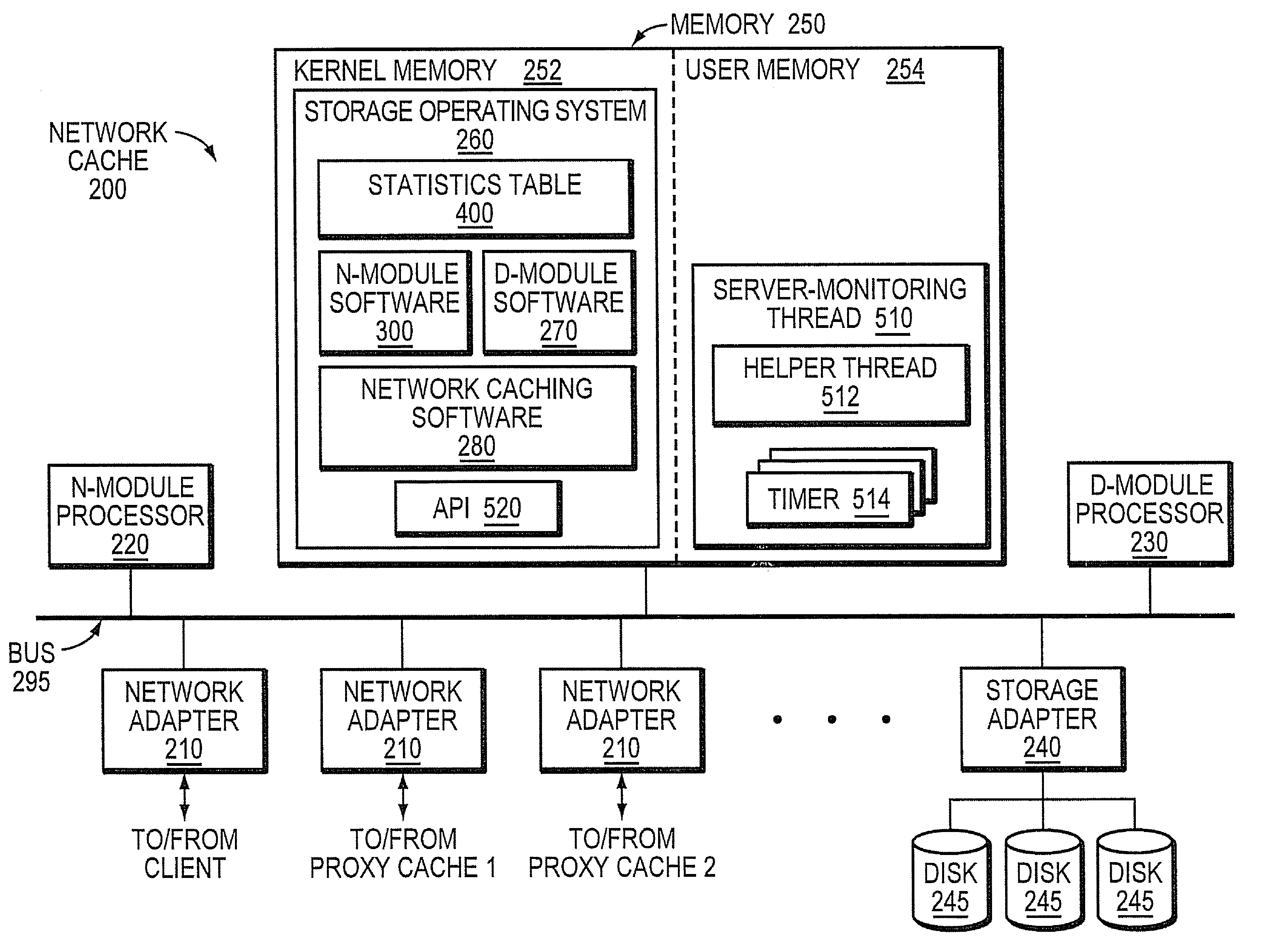
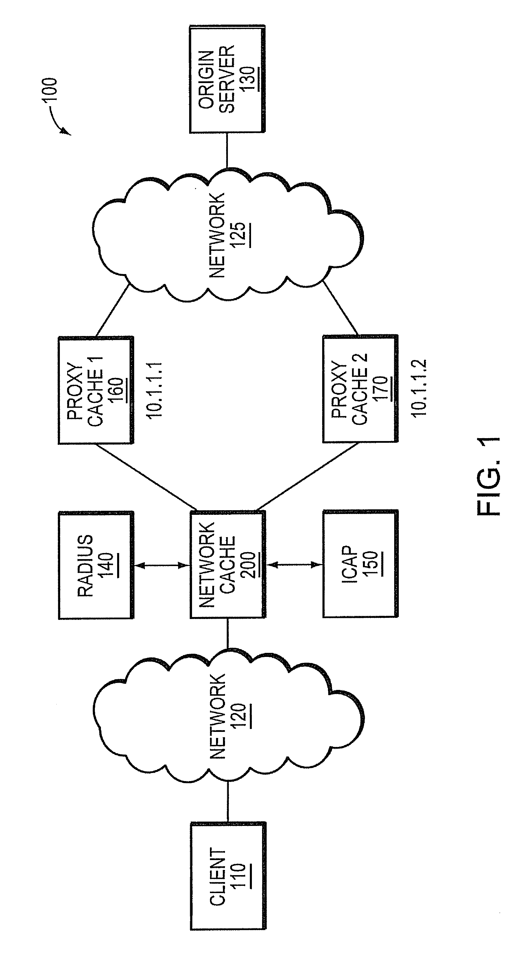
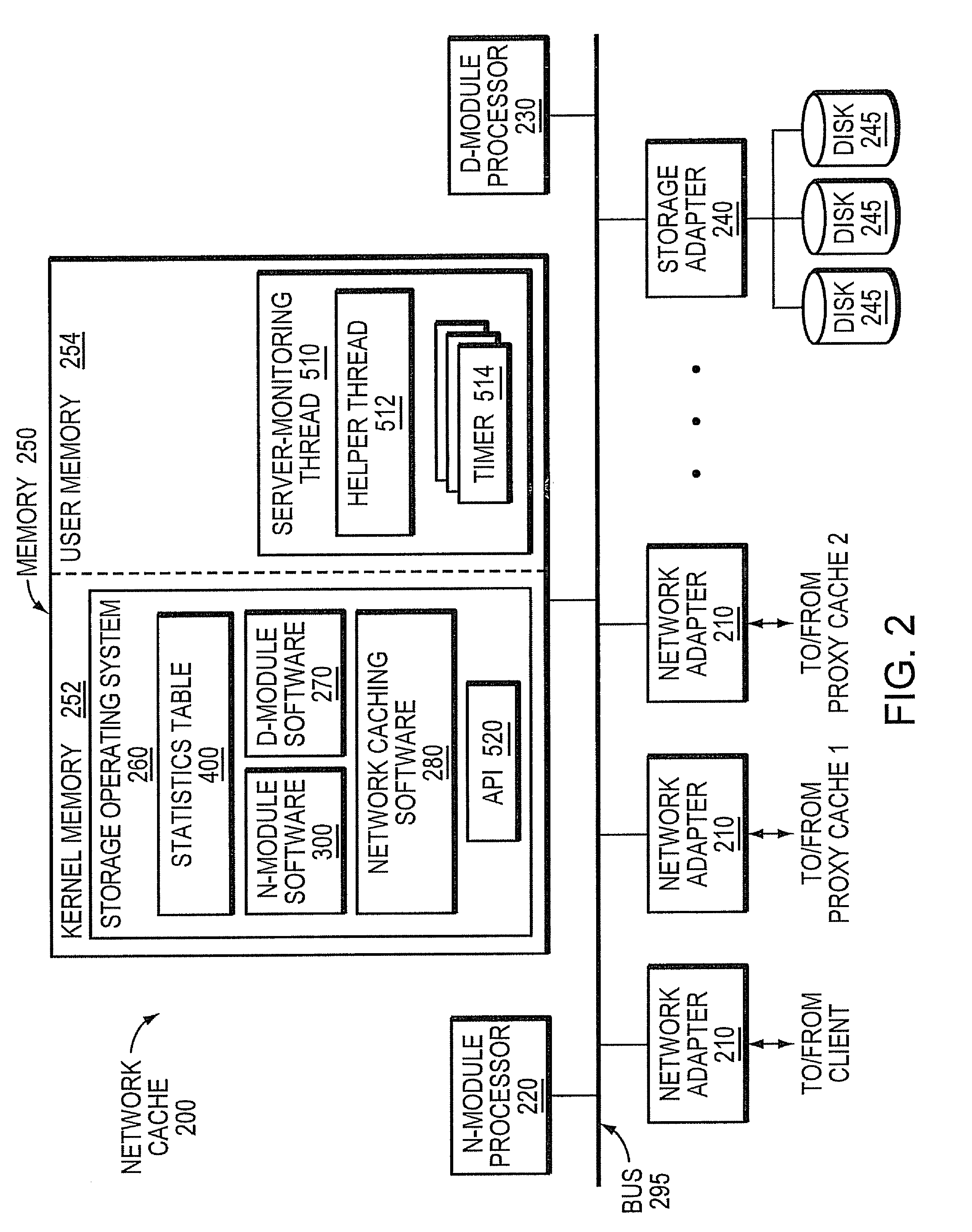
[0027]FIG. 1 illustrates an exemplary computer network 100 in which an illustrative embodiment of the invention may be deployed. The network includes at least one client 110 that is coupled to a network cache 200, e.g., through a network 120. In other embodiments, the client may be directly connected to the network cache. The cache 200 may be configured to operate in a forward or reverse proxy mode, and provides the client with faster access to a set of data objects, such as files, than if the client were to access those objects directly from an origin server 130, e.g., connected to the network 125.

[0028]The exemplary network 100 is arranged as a two-level cache hierarchy in which the network cache 200 stores a subset of the files contained in the higher-level proxy caches 160 and 170, respectively labeled “proxy cache 1” and “proxy cache 2.” The higher-level proxy caches, in turn, store a subset of the files available in the origin server 130. Besides the proxy caches 160 and 170, ...


PUM


Abstract

A software framework configured to execute in a computer system and adapted to monitor statistics associated with one or more servers coupled to the computer system is disclosed. A data structure is configured to store statistics associated with the one or more servers coupled to the computer system. A server-monitoring thread is configured to update at least some of the statistics stored in the data structure, the server-monitoring thread to execute on a processor of the computer system. An application programming interface (API) responsive to a plurality of software modules executes in the computer system, the API is configured to process requests from the plurality of software modules for (i) adding or removing servers in the data structure or (ii) accessing statistics from the data structure. The computer system may be a network cache.

Description

RELATED APPLICATION[0001]This application is a divisional of U.S. patent application Ser. No. 11 / 294,664, filed on Dec. 5, 2005 by Ravi Krishna et al., titled SERVER MONITORING FRAMEWORK, which is now issued as U.S. Pat. No. 7,653,722 on Jan. 26, 2010, which is hereby incorporated herein by reference.FIELD OF THE INVENTION[0002]The present invention generally relates to monitoring server statistics and, more specifically, to a novel framework through which multiple software modules can register servers to monitor and access statistical information associated with their registered servers.BACKGROUND OF THE INVENTION[0003]In general, a server may be configured to provide information to one or more clients according to a client / server model of information delivery. In this model, the server is a storage system that typically contains one or more mass storage devices, such as magnetic hard disks, in which information may be stored and retrieved as desired. The server is usually deployed...

Claims


Application Information

Patent Timeline
Patent Type & Authority Patents(United States)
IPC IPC(8): G06F15/16G06F12/00
CPCG06F17/30902H04L43/04H04L43/06H04L43/0864G06F16/9574
Inventor KRISHNA, RAVISHAH, VANDANA
Owner NETWORK APPLIANCE INC
Learn More