Connecting structure to cell of voltage detecting connector and fuel cell

a technology of voltage detection and connecting structure, which is applied in the direction of fuel cells, cell components, fuel cell groupings, etc., can solve the problems of inability to detect the cell voltage of the end cell, the terminal is not moveable, and the difficulty of obtaining electric power sufficient to drive an automobile, etc., to achieve the reduction of the number of terminals, the effect of maintaining the necessary detecting accuracy and reducing the increase of weight and cos

Inactive Publication Date: 2011-09-27
HONDA MOTOR CO LTD
View PDF15 Cites 2 Cited by
  • Summary
  • Abstract
  • Description
  • Claims
  • Application Information

AI Technical Summary

Benefits of technology

[0016]Therefore, it is an object of the present invention to provide a connecting structure to the cell of a voltage detecting connector which can prevent increase in weight due to terminals and increase of cost, while detecting all of the cell voltages and maintaining gaps between terminals, and a fuel cell.
[0017]In addition, it is another object of the present invention to provide a connecting structure to the cell of a voltage detecting connector which can detect the cell voltage at both ends of the stacked body, while prevent increase in the number of parts, cost, stacking width, and weight, and a fuel cell.

Problems solved by technology

Incidentally, it is difficult to obtain electric power sufficient to drive an automobile from one fuel cell.
Moreover, patent document 2 (Japanese Unexamined Patent Application, First Publication No. 2003-86219) discloses technology of clipping a terminal holder which holds terminals disposed on separators of cells of a fuel cell, thereby making the terminals unmovable.
However, hitherto, there were the following problems.
However, there are the following problems in the prior art.
As a result, in the case of detecting the cell voltage of the end cell of a stacked body in which plural cells are stacked, there is no cell adjoining thereto, and it is impossible to detect the cell voltage of the end cell.
Thus, it is necessary to dispose separately, a separator, a terminal, and a connector, which are not related to power generation, and the number of parts increases, thereby increasing cost, stacking width, and weight.

Method used


Image

  • Connecting structure to cell of voltage detecting connector and fuel cell
  • Connecting structure to cell of voltage detecting connector and fuel cell
  • Connecting structure to cell of voltage detecting connector and fuel cell

Examples


Embodiment Construction

[0044]Hereinafter, the connecting structure to a cell of the voltage detecting connector and fuel cell in one preferred embodiment of the present invention will be explained with reference to drawings.

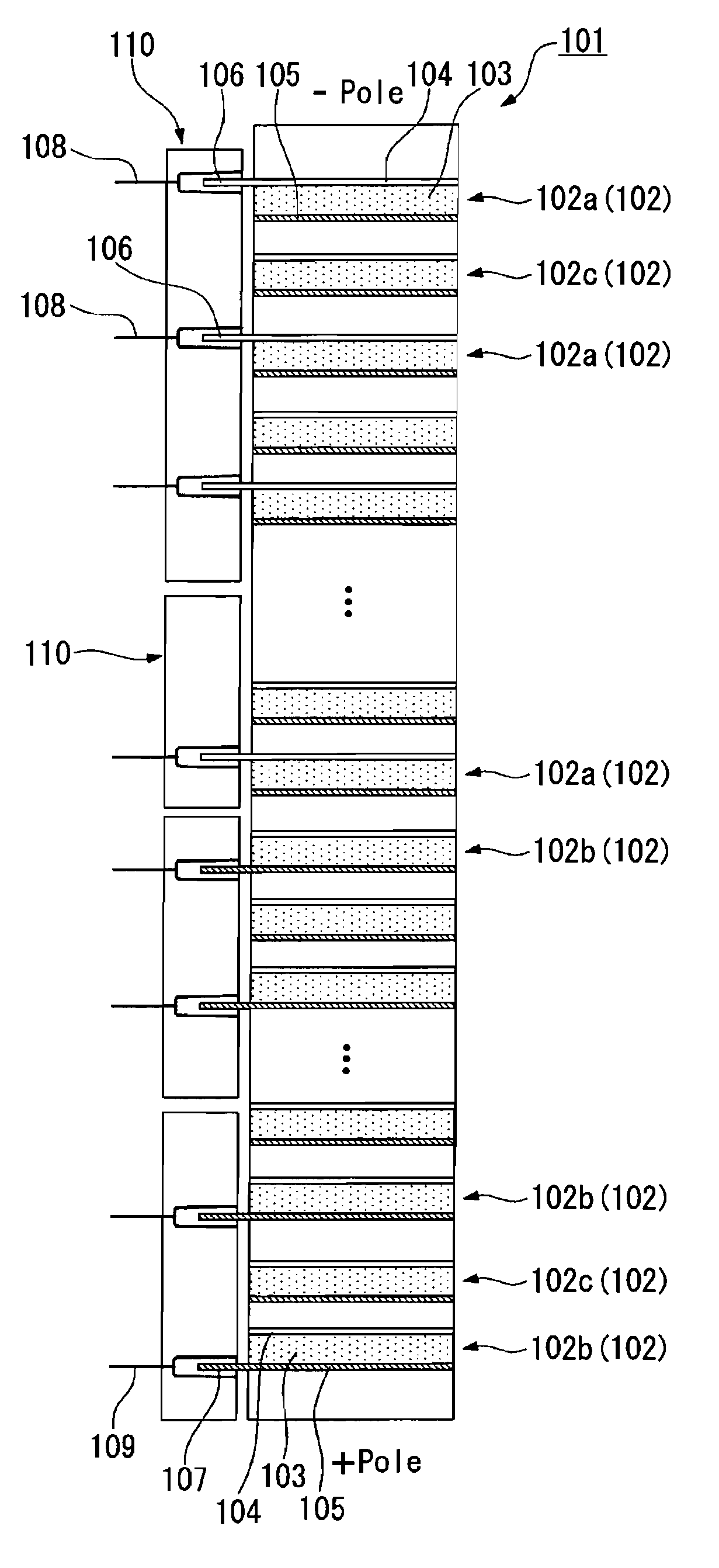
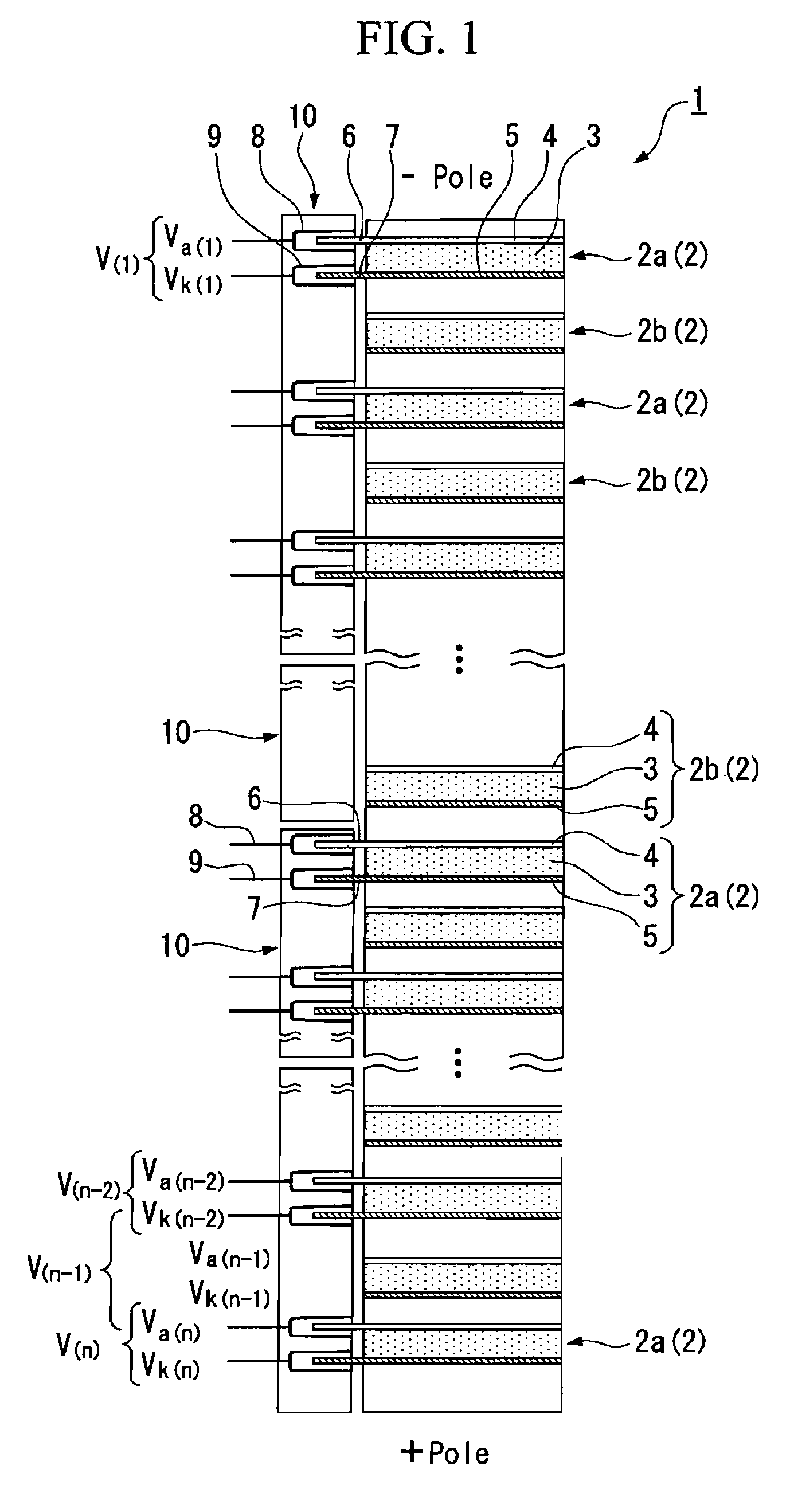
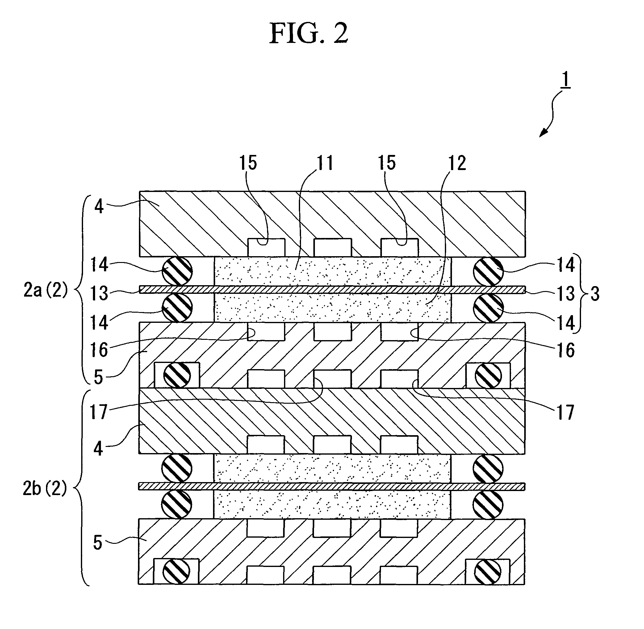
[0045]FIG. 1 is a sectional view of the principal part of a cell connecting apparatus equipped with a fuel cell and a voltage detecting connector connected to the fuel cell in one preferred embodiment of the present invention. As shown in this figure, a fuel cell 1 is constituted from a plurality of cells 2 which are stacked in a predetermined numbers (in this case, n). Each cell 2 is constituted by sandwiching a membrane electrode structure 3 with separators 4 and 5.

[0046]The fuel cell 1 in this embodiment is equipped with first cells 2a (2) in which terminals 6 and 7 for measuring voltage are disposed on separators 4 on anode electrode 11 sides (refer to FIG. 2) and separators 5 on cathode electrode 12 sides (refer to FIG. 2) respectively, and second cells 2b (2) which have terminals...


PUM

PropertyMeasurementUnit
voltageaaaaaaaaaa
electrical voltageaaaaaaaaaa
electric poweraaaaaaaaaa

Abstract

A voltage detecting connecting structure and fuel cell has connectors which are in contact with terminals connected to the fuel cell. An embodiment of the fuel cell includes first cells which have the terminals at an anode and a cathode respectively, and second cells which have terminals in neither an anode plate nor a cathode, stacked alternately. Another embodiment of the fuel cell includes first cells with terminals provided only to anode sides thereof, and second cells with terminals provided only to cathode sides thereof, the first cells being stacked from one end of the fuel cell and the second cells being stacked from the other end of the fuel cell.

Description

BACKGROUND OF THE INVENTION[0001]1. Field of the Invention[0002]The present invention relates to a connecting structure to a cell of an electrical voltage detecting connector which is connected to a fuel cell constituted by laminating plural cells having an anode and a cathode, for detecting electrical voltage of the cell, and to a fuel cell.[0003]Priority is claimed on Japanese Patent Application No. 2004-235153, filed Aug. 12, 2004, and Japanese Patent Application No. 2004-235154, filed Aug. 12, 2004, the contents of which are incorporated herein by reference.[0004]2. Description of Related Art[0005]In recent years, fuel cells are attracting attention as a new source of power, such as for an automobile. In general, a fuel cell consists of a membrane electrode architecture (MEA) in which an anode electrode (negative electrode) and a cathode electrode (positive electrode) are disposed on either side of a solid polymer electrolyte membrane respectively, and a pair of separators which...

Claims


Application Information

Patent Timeline
Patent Type & Authority Patents(United States)
IPC IPC(8): H01M8/24H01M8/04
CPCH01M8/0247H01M8/242H01M8/2465H01M8/0273H01M2008/1095Y02E60/50H01M8/2457H01M8/241H01M8/0297
Inventor ARIYOSHI, TOSHIAKIKONDO, JUN
Owner HONDA MOTOR CO LTD
Why Eureka
Try Eureka