Method and system for linking front and rear images in a document reader/imager

a document reader/imager and front and rear image technology, applied in the field of document processing, document imaging, magnetic ink character recognition, can solve the problem that conventional approaches to micr typically involve rather complex schemes, and achieve the effect of reducing the likelihood of accidental association

Inactive Publication Date: 2011-09-20
DIGITAL CHECK CORP
View PDF126 Cites 13 Cited by
  • Summary
  • Abstract
  • Description
  • Claims
  • Application Information

AI Technical Summary

Benefits of technology

[0012]It is an object of the invention to provide an improved method and system for linking front and rear images in ...

Problems solved by technology

In fact, conventional approaches to MICR typically involve rather complex schemes for controlling the velocity of the document or attempting...

Method used


Image

  • Method and system for linking front and rear images in a document reader/imager
  • Method and system for linking front and rear images in a document reader/imager
  • Method and system for linking front and rear images in a document reader/imager

Examples


Embodiment Construction

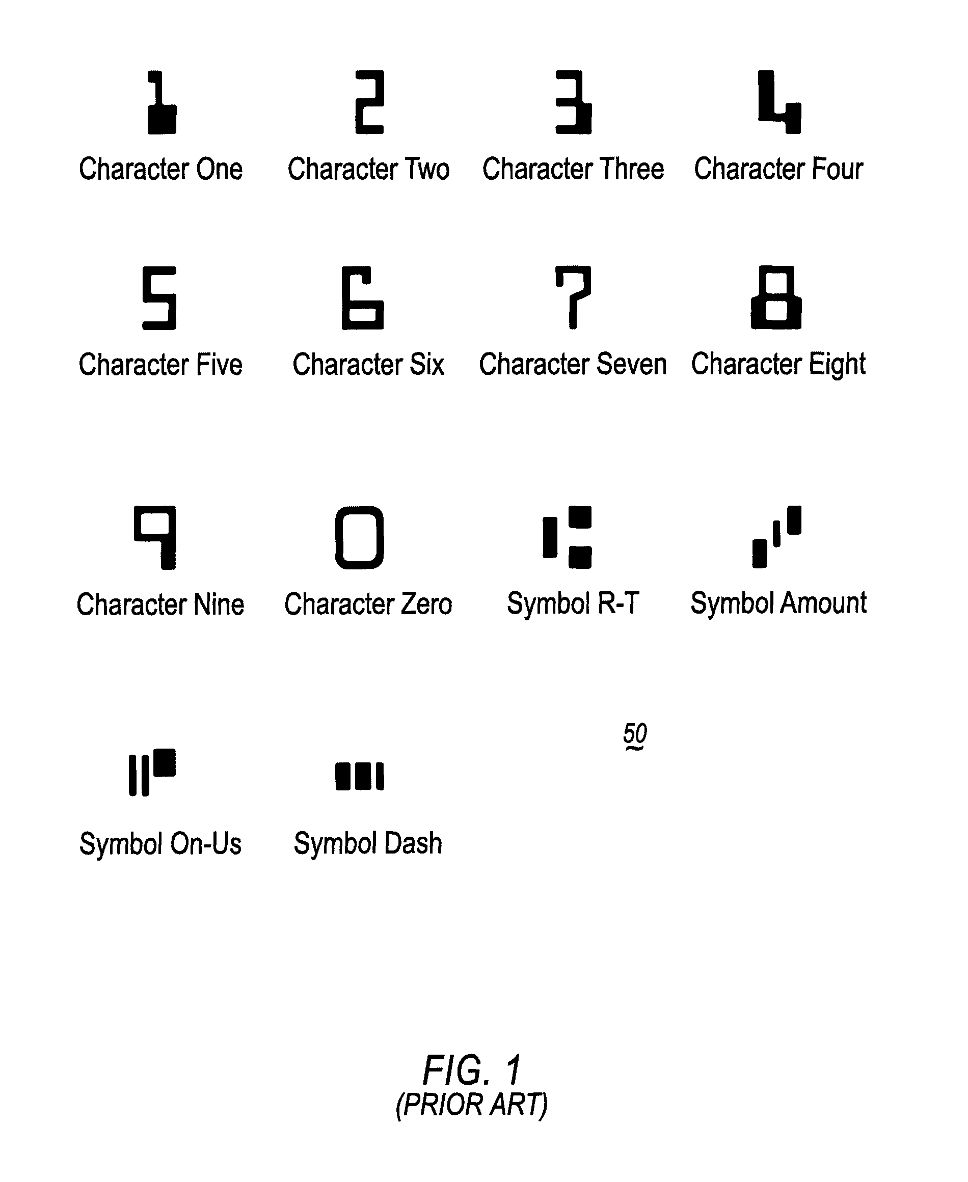
[0025]FIG. 1 illustrates the E-13B character set at 50. The character set 50 contains ten characters and four symbols as defined in the ANSI X9.27-2000 “Print and Test Specifications for Magnetic Ink Printing (MICR).” When used on a document for automated machine reading, the characters and symbols in the set must be printed using magnetic ink. ANSI X9.27 defines the dimensions of each character / symbol and the expected nominal waveform peak position and relative amplitude of waveform peaks.

[0026]FIGS. 2A-2N demonstrate the waveform details of each of the characters / symbols shown in FIG. 1 when each character / symbol is moved past a single gap magnetic read head at a given constant velocity. FIG. 2A shows the waveform 60 for the character “1” as the character is moved past the read head. FIG. 2B shows the waveform 62 for the character “2” as the character is moved past the read head. FIG. 2C shows the waveform 64 for the character “3” as the character is moved past the read head. FIG....


PUM


Abstract

A method for linking front and rear images in a document processing system involves linking the front and rear images by a magnetic ink character code line. The document processing system includes an imaging device and a magnetic ink character recognition (MICR) reader. The method comprises capturing a first image and first MICR waveform for the front side of the document, and capturing a second image and second MICR waveform for the rear side of the document. A forward recognition algorithm is applied to the first waveform to produce a first code line. A reverse recognition algorithm is applied to the second waveform to produce a second code line. The reverse recognition algorithm considers the second waveform as resulting from the document being read from the rear side of the document when processing the second waveform.

Description

BACKGROUND OF THE INVENTION[0001]1. Field of the Invention[0002]The invention relates to document processing, document imaging, and magnetic ink character recognition. The invention further relates to hand-operated document readers / imagers, and to methods and systems for linking front and rear images in a document reader / imager.[0003]2. Background Art[0004]A typical document processing system includes a feeder and a separator in the document-feeding portion of the system, and a series of roller pairs or belts in the document-transporting portion of the system. In the feeding portion of the system, the feeder acts with the separator to feed documents singly, in order, from a stack. In the transporting portion of the system, the roller pairs and / or belts convey the documents, one at a time, past other processing devices such as readers, printers, and sorters that perform operations on the documents. The feeder is typically a feed wheel, but may take other forms. The separator may be a...

Claims


Application Information

Patent Timeline
IPC IPC(8): G06K9/46G06K7/08G06Q40/00
CPCG06K7/084G06K9/186G06K9/3208G06Q20/042G06K2017/0038G06V30/2253G06V10/242
Inventor GUDENBURR, JOHN C.MOORE, MICHAEL J.KOZLOWSKI, WILLIAM L.HUTSON, SAMMY C.
Owner DIGITAL CHECK CORP
Why Eureka
Try Eureka