
Fully fibrous structure friction material

a technology of friction material and fibrous structure, which is applied in the direction of friction lining, manufacturing tools, other chemical processes, etc., can solve the problems of not being suitable for high-energy applications, and achieve the effect of durable and high-performance friction material

Active Publication Date: 2011-09-20
BORGWARNER INC
View PDF362 Cites 10 Cited by
  • Summary
  • Abstract
  • Description
  • Claims
  • Application Information

AI Technical Summary

Benefits of technology

The present invention relates to a friction material that has a fibrous base material with dispersed friction modifying particles. The fibrous base material is made of aramid fibers, carbon fibers, cellulose fibers, and other fibrous materials. The friction material has improved friction characteristics, including smooth shifts, low lining loss, and high heat resistance. The fibrous base material has pore sizes that aid in permeability and porosity. The friction material also has improved "hot spot" resistance, meaning it can withstand higher temperatures. The fibrous base material has a soft and uniform surface, and the friction modifying particles are evenly distributed throughout the material. The friction material has improved performance in high-energy applications and is suitable for use in brakes and transmissions.

Problems solved by technology

Both commercially available brake linings and transmission materials were investigated and proved not to be suitable for use in high-energy applications.

Method used

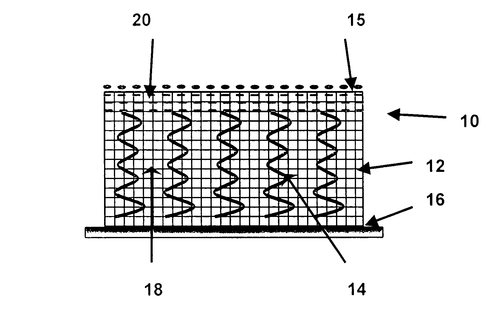
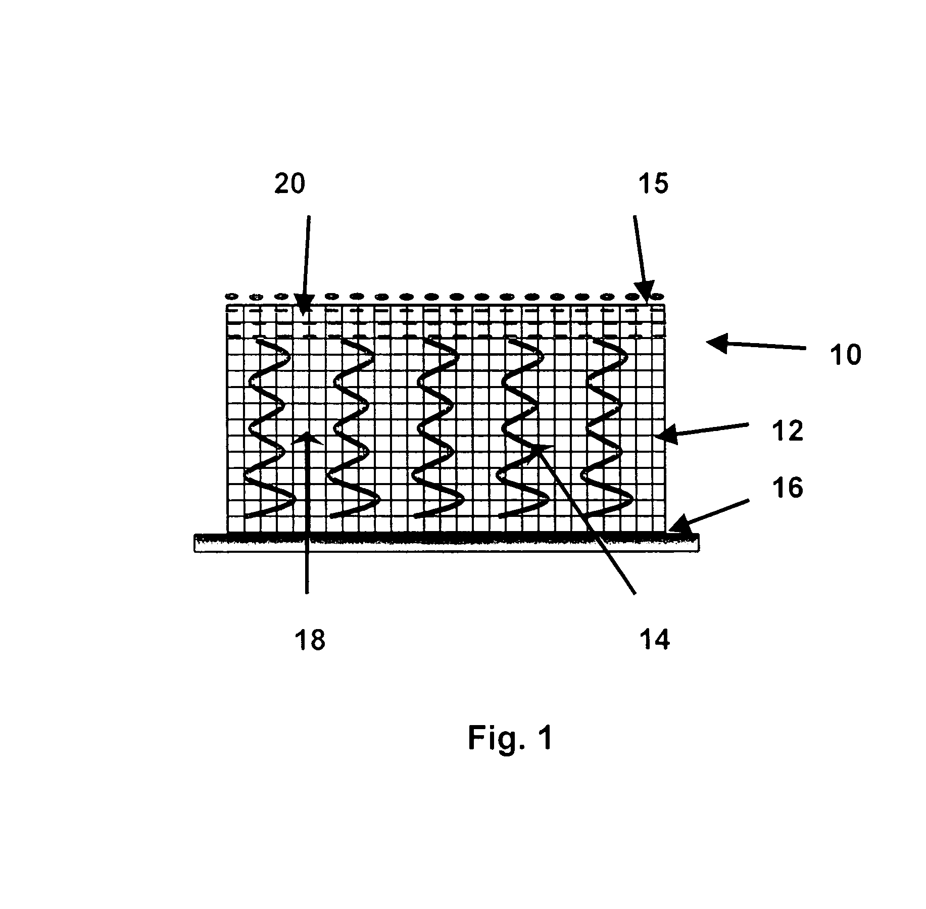
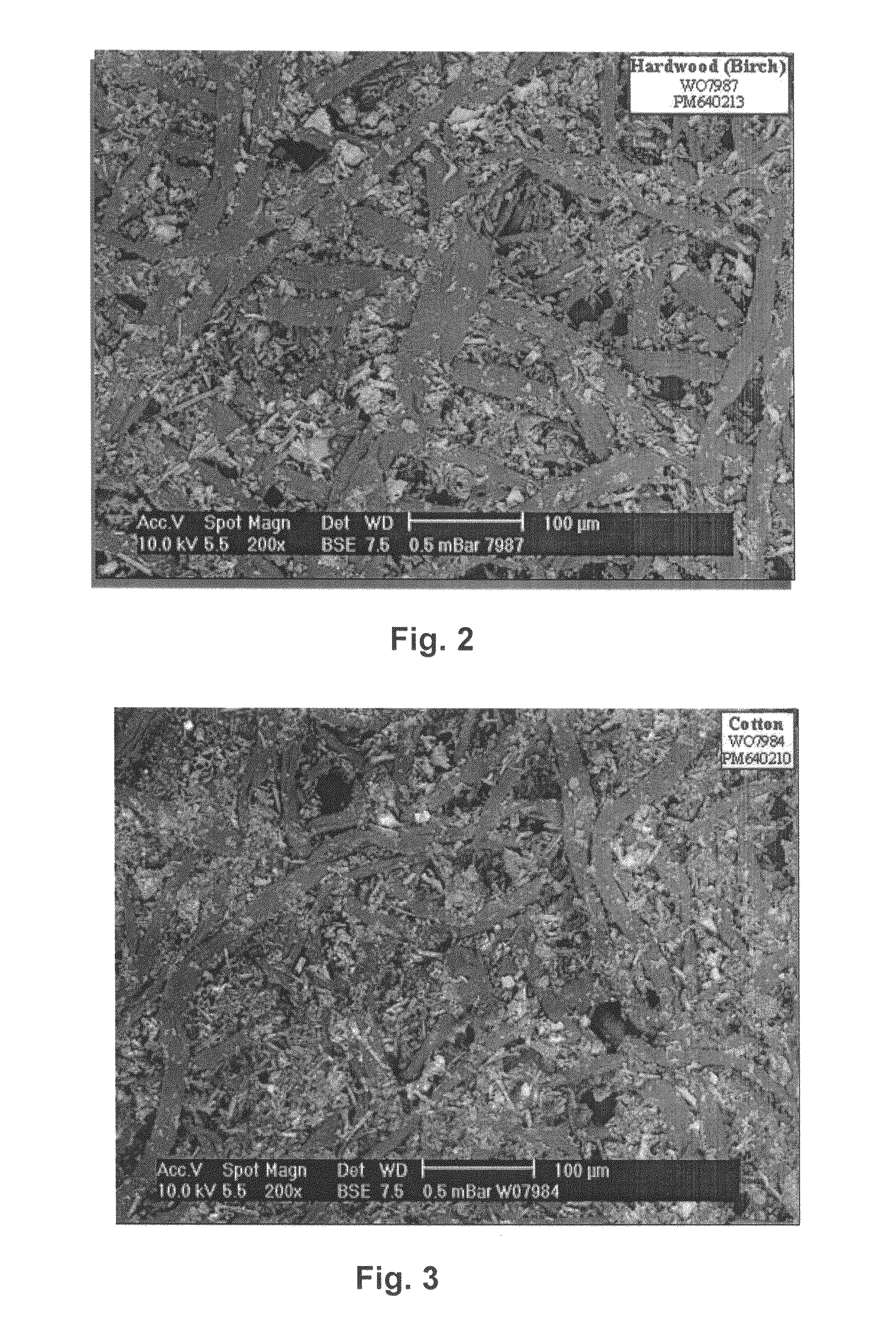

Image

  • Fully fibrous structure friction material
  • Fully fibrous structure friction material
  • Fully fibrous structure friction material

Examples


examples

[0116]The friction materials of the present invention are especially suited for shifting clutch applications that have special requirements. These requirements include high coefficient of friction characteristics, hot spot resistance, good smoothness and permeability characteristics as shown by good torque curves and good Mp-v curves, low lining loss as shown by low compression set and high strength, and large pore sizes within the fully fibrous base material for better permeability as shown by coefficient of friction stability.

[0117]FIGS. 6 and 7 are SEMs (at ×11 and ×500) of one example, Example 1, of the present invention showing a top surface (felt side) of a fully fibrous base friction material having a permeating or penetrating gradient of friction modifying particles that have substantially dispersed therein. The FIGS. 6 and 7 show that the top surface is partially covered such that open channels are maintained in the fully fibrous base material.

[0118]FIG. 8 is an SEM at ×500...

example i

[0121]Table 1 shows the formulations for an Example 1 of the present invention and Comparative examples A, B and C.

[0122]

TABLE IOneMaterialEmbodimentFurnish %Ex. 1of Ex. 1Compar. ACompar. BCompar. CAramid fiber -60–7020–25fibrillated6623Aramid fiber -30–4040–50less3545fibrillatedCSF 625Carbon fiber 5–159Cotton fiber10–1512.525–3520–3015–25312520Graphite20–2515–2515–2521.52020Silica-celite20–3038824.5Silica-15–25symmetrical20shapedCellulose10–15Wood-eucalyptus12.5Friction9 lbs9 lbs9 lbs as aModifyingdisperseddispersedtop coatingParticleswithinwithinlayerBasis Weight123 + 9 lbs123 + 9 lbs154154154 + 9 lbs

example ii

[0123]The correlation between the test levels for “Low Energy / High Temperature” and “High Energy / High Temperature” as compared to the dynamic coefficients of friction for Example 1, Compar. A, Compar. B., and Compar. C. is shown in FIG. 10. The Tables 2a and 2b below show the material properties of modulus, permeability, roughness and COF for the low energy region (Table 2a-levels I-L) and the high energy regions (Table 2b-levels M-P), where 1 is lowest and 4 is highest.

[0124]

TABLE 2aLow EnergyRegionModulusPermeabilityRoughnessCOFCompar. C1214Example 12343Compar. B4422Compar. A3131

[0125]

TABLE 2bHigh EnergyRegionModulusPermeabilityRoughnessCOFCompar. C1214Example 12342Compar. B4423Compar. A3131


PUM

PropertyMeasurementUnit
sizeaaaaaaaaaa
sizeaaaaaaaaaa
depthaaaaaaaaaa

Abstract

The present invention relates to a friction material having a fully fibrous content fibrous base material. The base material has dispersed therethrough, in a penetrating gradient, a desired amount of friction modifying particles.

Description

BACKGROUND ART[0001]New and advanced transmission systems and braking systems are being developed by the automotive industry. These new systems often involve high-energy requirements. Therefore, the friction materials technology must be also developed to meet the increasing energy requirements of these advanced systems.[0002]In particular, new high performance, durable friction materials are needed. The new friction material must be able to withstand high speeds wherein surface speeds are up to about 65 m / seconds. Also, the friction material must be able to withstand high facing lining pressures up to about 1500 psi. It is also important that the friction material be useful under limited lubrication conditions.[0003]The friction material must be durable and have high heat resistance in order to be useful in the advanced transmission and braking systems. Not only must the friction material remain stable at high temperatures, it must also be able to rapidly dissipate the high heat tha...

Claims


Application Information

Patent Timeline
Patent Type & Authority Patents(United States)
IPC IPC(8): B28B23/00D04H1/00B29D22/00B32B1/08B65D1/00F16D69/02
CPCF16D69/026F16D2200/0065Y10T428/1397F16D2200/0091Y10T428/1372F16D2200/0069Y10T428/249924C09K3/14D06M15/693
Inventor LAM, ROBERT C.OH, IN SEOK
Owner BORGWARNER INC
Learn More