
Cryocooler split flexure suspension system and method

a technology of suspension system and cryogenic cooler, which is applied in the field of cryogenic coolers, can solve the problems of increasing the overall design of the system, increasing the mass and volume relative to other available systems, and extremely inefficient arrangement, so as to reduce the package size, increase the resistance to cantilevered mass sag, and reduce the package size

Active Publication Date: 2011-09-13
RAYTHEON CO
View PDF13 Cites 1 Cited by
  • Summary
  • Abstract
  • Description
  • Claims
  • Application Information

AI Technical Summary

Benefits of technology

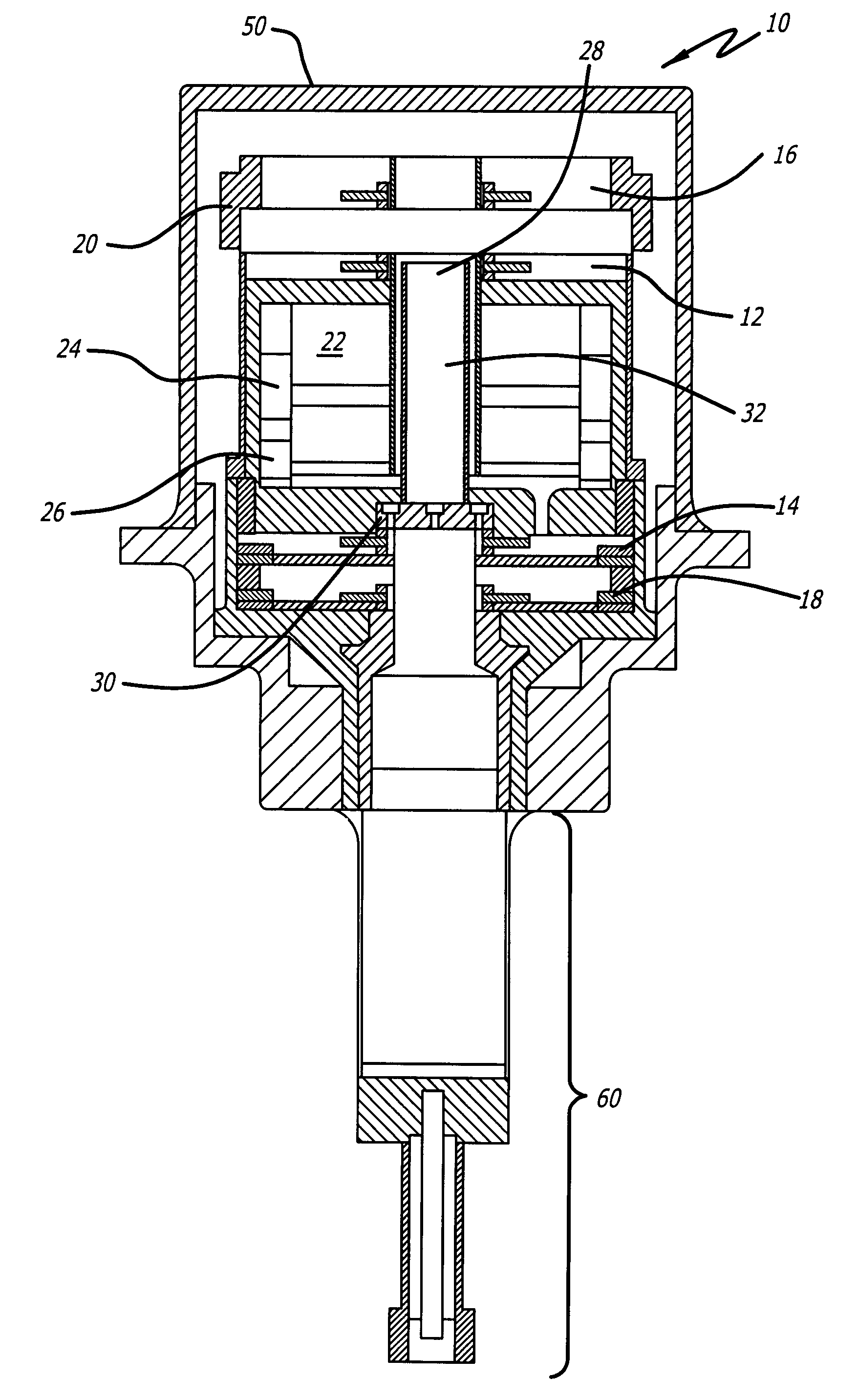
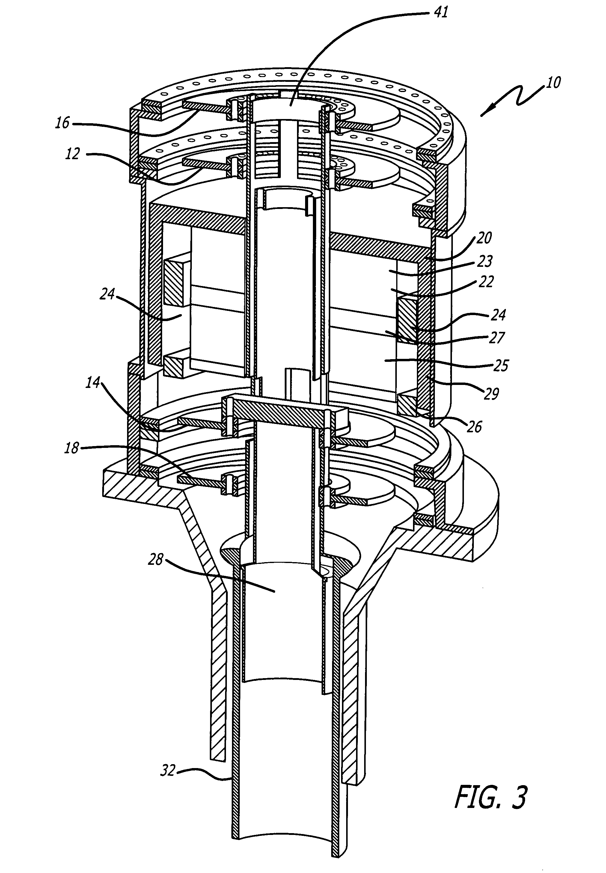
[0014]In the illustrative embodiment, two independently moving flexure systems, each consisting of two discrete flexure stacks separated by an appropriate distance, are split across a single magnetic structure, decreasing package size and greatly increasing resistance to cantilevered mass sag due to external forces. A series of concentrically oriented flexure connecting shafts are provided that allow two independently moving flexure assemblies to be split across a single motor. A series of connectors are included on the forward side of the motor that pass through the outer shaft and allow the inner connecting shaft to be mounted to its flexures without interference. A series of close-out connections are included on the aft flexure stacks that makes assembly possible, providing firm mechanical connections without interference.
[0015]Essentially, this invention allows the normally unused space between the two flexure stacks of each flexure system to be occupied by the cryocooler motor's magnetic circuit; little unused volume is necessary for the spacing of the flexures, allowing for a reduction of package size while maintaining the mechanical advantage necessary to prevent sag of cantilevered masses. The invention can be assembled and aligned at a lower level of integration as compared to typical Stirling cryocooler mechanisms with an alignment procedure that offers inherent simplicity, accuracy, and stability.

Problems solved by technology

However, these strengths come at the cost of increased mass and volume relative to other available systems.
However, this arrangement is extremely inefficient from a packaging standpoint.
This spacing between flexure stacks adds significant length to the overall design.

Method used


Image

  • Cryocooler split flexure suspension system and method
  • Cryocooler split flexure suspension system and method
  • Cryocooler split flexure suspension system and method

Examples


Embodiment Construction

[0024]Illustrative embodiments and exemplary applications will now be described with reference to the accompanying drawings to disclose the advantageous teachings of the present invention.

[0025]While the present invention is described herein with reference to illustrative embodiments for particular applications, it should be understood that the invention is not limited thereto. Those having ordinary skill in the art and access to the teachings provided herein will recognize additional modifications, applications, and embodiments within the scope thereof and additional fields in which the present invention would be of significant utility.

[0026]U.S. patent application Ser. No. 11 / 805,320, filed May 16, 2007 by R. C. Hon et al. and entitled STIRLING CYCLE CRYOGENIC COOLER WITH DUAL COIL SINGLE MAGNETIC CIRCUIT MOTOR, the teachings of which are incorporated herein by reference, discloses and claims a novel and advantageous dual-coil, single magnetic circuit Stirling cryocooler design th...


PUM


Abstract

A cryocooler in which two independently moving flexure systems are split across a single magnetic structure, decreasing package size and increasing resistance to cantilevered mass sag due to external forces. A series of concentrically oriented flexure coupling shafts are provided that allow two independently moving flexure assemblies to be split across a single motor. A series of connectors are included on the forward side of the motor that pass through the outer shaft and allow the inner connecting shaft to be mounted to its flexures without interference. A series of close-out connections are included on the aft flexure stacks that makes assembly possible, providing firm mechanical connections without interference.

Description

BACKGROUND OF THE INVENTION[0001]1. Field of the Invention[0002]The present invention relates to cryogenic coolers. More specifically, the present invention relates to systems and methods for suspending and supporting cryogenic coolers.[0003]2. Description of the Related Art[0004]Space infrared sensor systems often require use of a cryogenic cooling subsystem to achieve increased sensor performance. Numerous types of cryogenic cooling subsystems exist, each having relatively strong and weak attributes compared to the other types. Certain space cryocoolers typically have efficiency, operational flexibility and vibration performance as strong suits. However, these strengths come at the cost of increased mass and volume relative to other available systems.[0005]For example, the application of flexure-borne moving assemblies is one of the most important developments in modern cryocoolers because the associated high amounts of radial stiffness allow for close-tolerance non-contacting cle...

Claims


Application Information

Patent Timeline
Patent Type & Authority Patents(United States)
IPC IPC(8): F25B9/00
CPCF25B9/14F25B2309/001
Inventor BELLIS, LOWELL A.HON, ROBERT C.
Owner RAYTHEON CO
Learn More