
Method and system for distributed measurement and compensation of chromatic dispersion in an optical network

a chromatic dispersion and optical network technology, applied in the field of optical networks, can solve the problems of limiting the reach of an optical link and the data rate, inefficient, intrusive and laborious, and the temporal spread of optical signals

Active Publication Date: 2011-09-06
WSOU INVESTMENTS LLC
View PDF12 Cites 10 Cited by
  • Summary
  • Abstract
  • Description
  • Claims
  • Application Information

AI Technical Summary

Benefits of technology

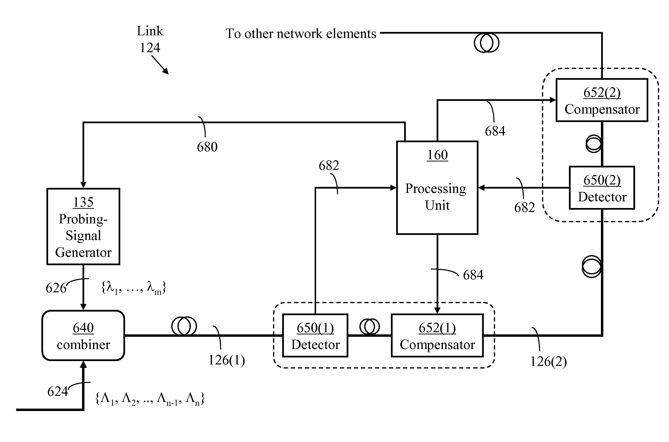
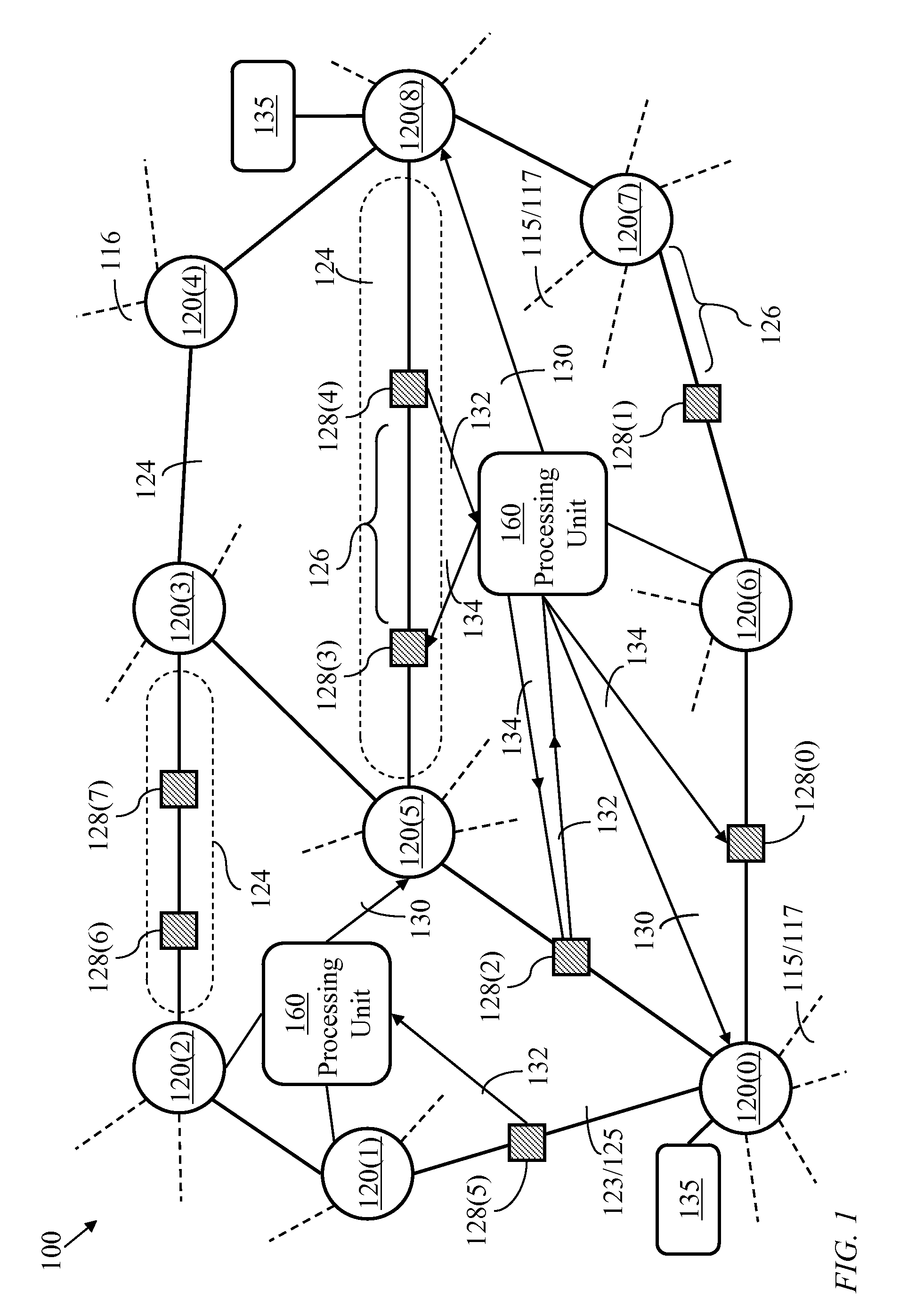
"The present invention provides a system and method for distributed measurement of chromatic dispersion in an optical network. The system includes a processing unit, probing-signal generator, and probing-signal detectors placed at various locations in the network. The probing-signal generator produces a periodic optical signal with different wavelengths during successive time intervals. The detectors measure the phase differences between the segments of the optical signal and send the data to the processing unit. The processing unit determines the chromatic dispersion between wavelengths corresponding to the successive time intervals. The system can be used to measure chromatic dispersion in a link or along a span of the network. The method allows for accurate measurement of chromatic dispersion and compensation in real-time."

Problems solved by technology

Chromatic dispersion results in different propagation speeds for optical signals of different wavelengths, which in turn causes temporal spread of optical signals and limits the reach of an optical link and the data rate carried by a wavelength channel within the link.
Such methods usually require a high-speed external modulator and external access to a fiber span under test in order to perform the chromatic-dispersion measurement, and are therefore inefficient, intrusive and labor intensive.

Method used


Image

  • Method and system for distributed measurement and compensation of chromatic dispersion in an optical network
  • Method and system for distributed measurement and compensation of chromatic dispersion in an optical network
  • Method and system for distributed measurement and compensation of chromatic dispersion in an optical network

Examples


Embodiment Construction

Terminology

[0056]Optical switching node: An optical switching node is a device for receiving optical signals from at least two input channels and directing each received optical signal to one of at least two output channels. The optical switching node considered herein may take the form of a space switch or a wavelength-channel add-drop multiplexer. The input channels may comprise channels arriving from another switching node and sharing input wavelength division multiplexed (WDM) links as well as channels from local data sources. The output channels may comprise channels directed to another switching node and sharing output WDM links as well as output channels leading to local data sinks. Herein, an optical switching node may be referenced as a “switching node” for brevity.

Optical Add-drop multiplexer: An optical add-drop multiplexer is a simplified optical switching node accommodating a small number of WDM links and often used in ring networks.

Transport module: A transport module ...


PUM


Abstract

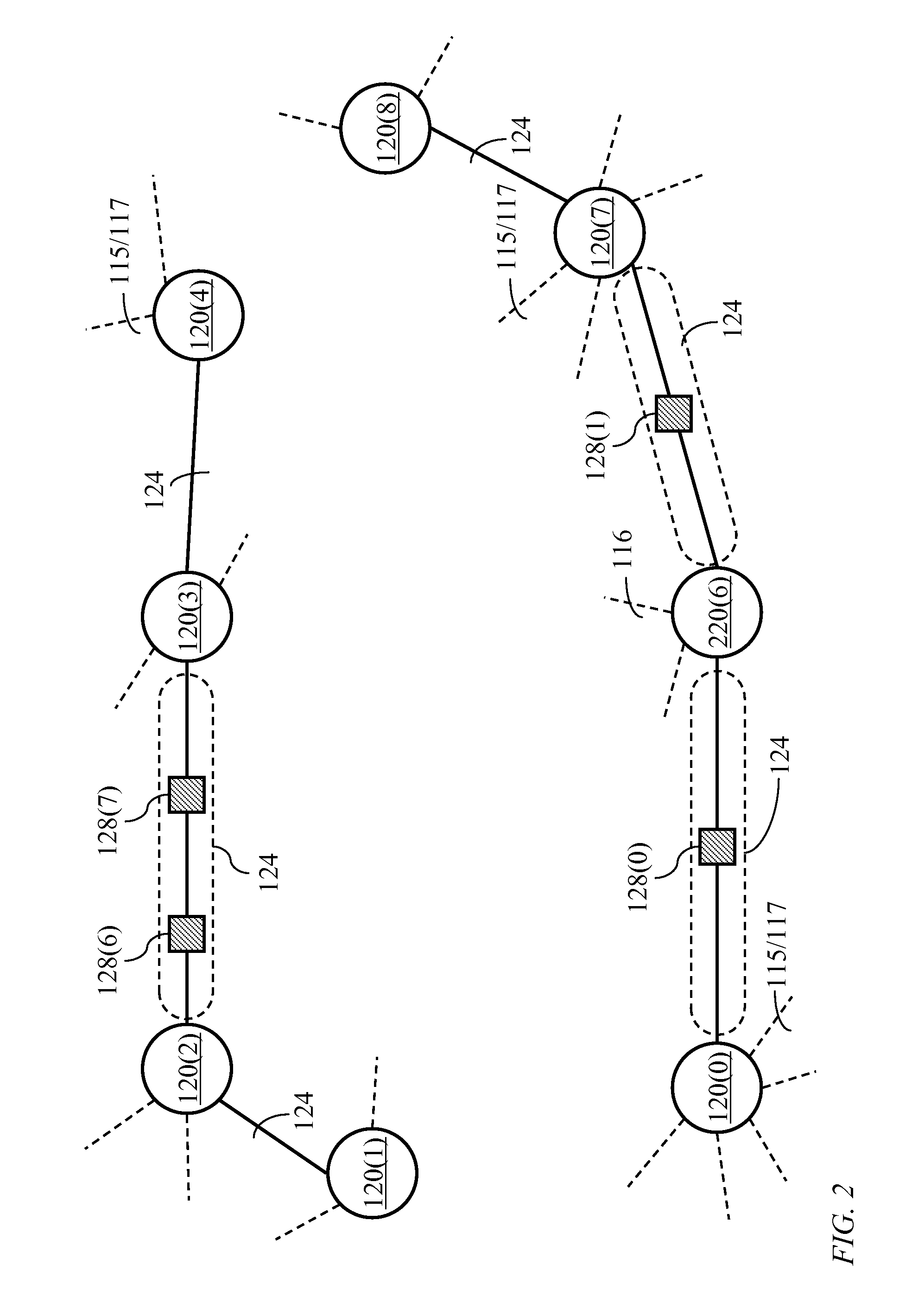
A method and apparatus for distributed measurement of chromatic dispersion in an optical network is disclosed. The network comprises optical switching nodes interconnected by optical links. An optical link may comprise multiple spans, each span ending in a transport module which comprises signal-processing components. At least one optical switching node has a probing signal generator transmitting an optical probing signal along a selected path in the network. Probing-signal detectors placed at selected transport modules determine chromatic-dispersion values and send results to a processing unit which determines appropriate placement of compensators or appropriate adjustments of compensators placed along the path. A preferred probing signal has the form of wavelength modulated optical carrier which is further intensity modulated by a periodic, preferably sinusoidal, probing tone. Variation in the phase-shift of the probing tone corresponding to variation of the wavelength of the optical probing signal determines chromatic-dispersion characteristics for different spans of the path.

Description

CROSS-REFERENCE TO RELATED APPLICATIONS[0001]This application claims priority to U.S. provisional application 60 / 885,909 to Wan et al entitled “Method and System for Distributed Measurement and Compensation of Chromatic Dispersion in Optical Networks”, which was filed on Jan. 21, 2007, which is incorporated herein by reference.FIELD OF THE INVENTION[0002]The invention relates to optical networks, and in particular, to a method and system for distributed measurement and compensation of chromatic dispersion in an optical network.BACKGROUND OF THE INVENTION[0003]Chromatic dispersion is caused by material dispersion, resulting from variation in the refractive index of an optical material, and waveguide dispersion, resulting from changes in the distribution of light between the core and the cladding of a single mode fiber. Accurate measurement of chromatic dispersion in optical transmission networks is of paramount importance to enable proper compensation. Chromatic dispersion results in...

Claims


Application Information

Patent Timeline
Patent Type & Authority Patents(United States)
IPC IPC(8): H04B10/00H04J14/08H04B10/08H04B10/12
CPCH04B10/0775H04B2210/075H04B2210/078
Inventor WAN, PING WAIREMEDIOS, DERRICKCHIMFWEMBE, PATRICK CHILUFYAKELLY, COLIN GEOFFREYBACQUE, JAMES BENSON
Owner WSOU INVESTMENTS LLC
Learn More