System for mitigating the effects of fiber dispersion by separate detection of two transmitted sidebands

a technology of fiber dispersion and transmission sideband, applied in the field of optical communication, can solve the problems of relative delay, inability to compensate for electrical dispersion of double sideband modulated signals, and degradation of system performance, so as to reduce polarization mode dispersion, improve optical spectral efficiency, and mitigate the effects of pmd

Inactive Publication Date: 2006-10-24
AT&T CORP
View PDF1 Cites 10 Cited by
  • Summary
  • Abstract
  • Description
  • Claims
  • Application Information

AI Technical Summary

Benefits of technology

[0006]In an optical fiber communication system, the signal will suffer dispersion as it travels along the transmission fiber. Dispersion causes smearing of the transmitted signal in the time domain and degrades the system performance. The degradation due to dispersion increases with the signal bandwidth. In long distance transmission systems, dispersion can also interact with non-linearities in the optical fiber to further impair transmission. Moreover, because the two sidebands mirror each other about the optical carrier frequency, chromatic dispersion causes opposite phase changes in the two sidebands when the signal is converted back into the electrical domain. This spectrum folding effect makes electrical dispersion compensation of a double sideband modulated signal impossible. Since the two sidebands contain duplicated information, one way to mitigate the effect of dispersion is to suppress the transmission of one of the sidebands to reduce the signal bandwidth, which has been proposed by others.
[0007]Dispersion compensating fiber (DCF) with opposite dispersion has been used in optical communication systems to compensate for chromatic dispersion. However, PMD is also associated with fiber. While chromatic dispersion is deterministic and can be compensated with DCF, PMD is a statistical effect, which cannot be compensated simply by using DCF. Even for chromatic dispersion compensation, electrical compensation may be more flexible and compact.
[0015]Optical single sideband (OSSB) transmission schemes have been previously proposed and demonstrated to mitigate the effects of PMD and improve optical spectral efficiency. This idea has been described in a previously filed patent application Ser. No. 09 / 625,791, filed Jul. 26, 2000 now abandoned, entitled METHOD AND SYSTEM FOR REDUCING POLARIZATION MODE DISPERSION USING SINGLE-SIDEBAND DATA GENERATION AND TRANSMISSION, commonly held and incorporated herein by reference. In the present invention, both sidebands in a double sideband transmitted signal are transmitted, but the two sidebands are detected separately and a diversity-combining receiver is used to improve the link robustness, especially for PMD immunity.
[0016]It is therefore an object of the present invention to improve link robustness by transmitting both sidebands of an amplitude modulated optical carrier.

Problems solved by technology

Dispersion causes smearing of the transmitted signal in the time domain and degrades the system performance.
This spectrum folding effect makes electrical dispersion compensation of a double sideband modulated signal impossible.
While chromatic dispersion is deterministic and can be compensated with DCF, PMD is a statistical effect, which cannot be compensated simply by using DCF.
Due to impurities, strains and imperfect symmetry in actual fibers, the polarization modes travel through the fiber at different speeds, causing relative delay.
That is, the two polarization modes arrive at different times, which degrades the performance.
The result of dispersion is to limit the transmission distance or the bandwidth that a fiber may provide.

Method used


Image

  • System for mitigating the effects of fiber dispersion by separate detection of two transmitted sidebands
  • System for mitigating the effects of fiber dispersion by separate detection of two transmitted sidebands
  • System for mitigating the effects of fiber dispersion by separate detection of two transmitted sidebands

Examples


Embodiment Construction

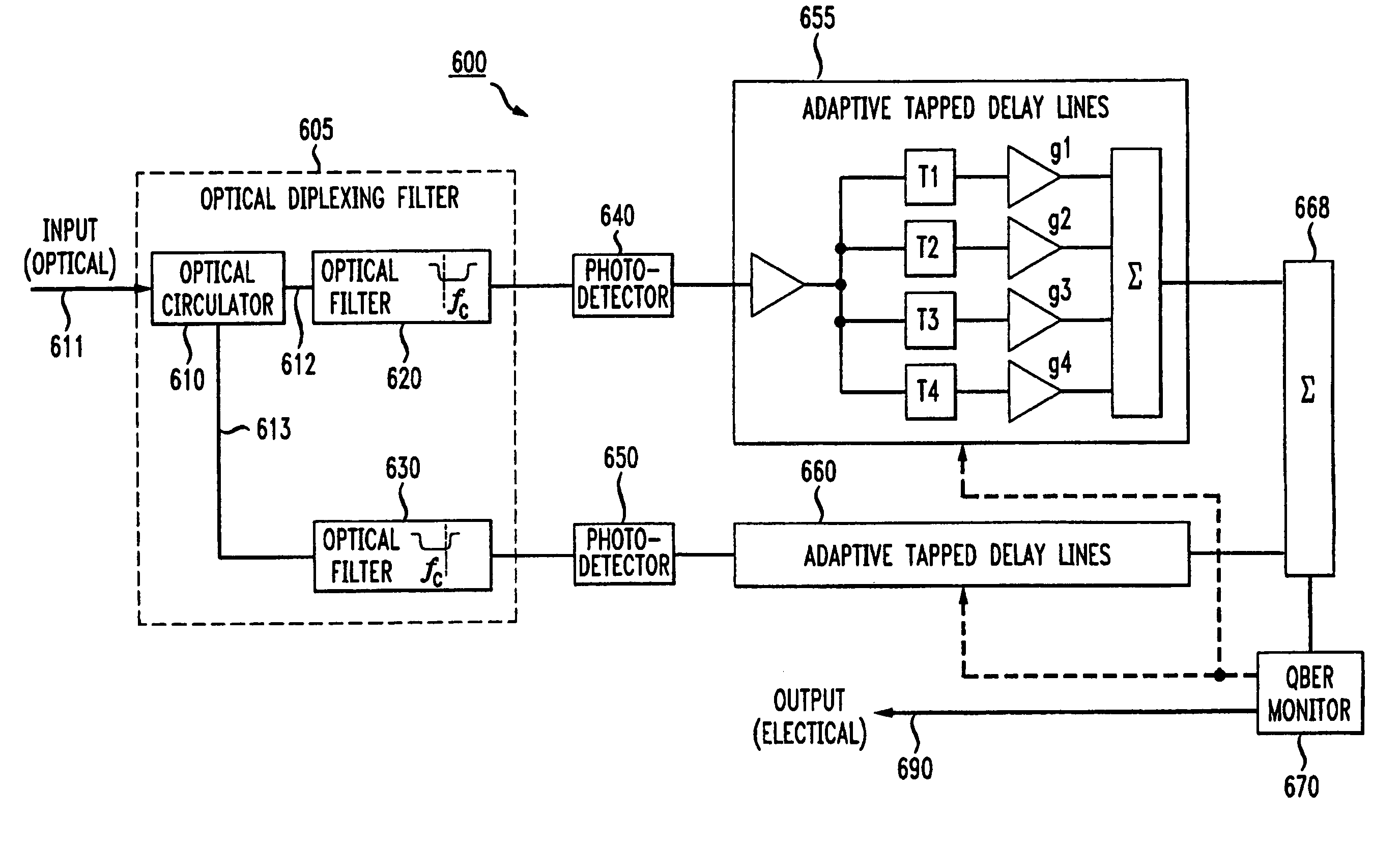
[0027]In a diversity receiver, which separately detects the two sidebands on an amplitude modulated optical carrier, the duplicated information in the two sidebands suffers different impairments during transmission. By selectively combining the recovered information from the two sidebands, one can achieve a better immunity against fiber dispersion impairments such as chromatic and polarization mode dispersions.

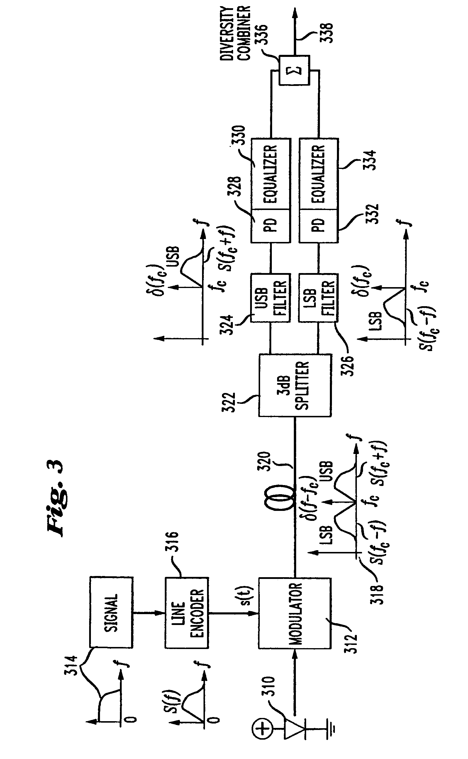
[0028]The present invention is illustrated in FIG. 3. The signal to be transmitted is optionally fed into a line encoder, which then amplitude modulates the optical carrier using a modulator. Both sidebands of the amplitude modulated signal are then transmitted over the optical fiber. The received signal is split into its two sidebands using an optical diplexing filter. In a manner analogous to an RF diplexor, the optical diplexing filter separates an input optical signal into two output signals, with different optical frequencies being routed to different output ports. FIG. 3...


PUM


Abstract

Link robustness, chromatic dispersion and polarization mode dispersion (PMD) immunity can be improved in fiber optical system by using a method for receiving an optical double sideband signal over an optical fiber system, comprising the steps of splitting the received optical double sideband signal into an upper sideband signal and a lower sideband signal, photodetecting the upper sideband and the lower sideband, equalizing the photodetected upper sideband signal and the lower sideband signal, and combining the equalized upper sideband signal with the equalized lower sideband signal. While PMD compensation is envisioned as a major application, one may also use the method and system for chromatic dispersion compensation or dispersion slope compensation in high bit rate systems, i.e. using dispersion compensation fiber (DCF) for coarse compensation and diversity receiver with electrical equalizer for fine tuning.

Description

[0001]This application is a continuation of U.S. application Ser. No. 09 / 722,646, now U.S. Pat. No. 6,959,154 filed on Nov. 28, 2000.FIELD OF THE INVENTION[0002]The invention relates generally to optical communications and particularly to a method and apparatus for improving link robustness by independently receiving and equalizing the two sidebands in a double sideband transmission system.BACKGROUND OF THE INVENTION[0003]There is a great deal of legacy fiber with high polarization mode dispersion (PMD) in the field. In fact, PMD is becoming a limiting factor for transmission systems with speeds of 10 Gbps or above, especially in systems using old fibers with high birefringence. There has been significant customer demand for 10 Gbps private lines. Without PMD compensation, many of these fibers may not support 10 Gbps wavelength channels. Also, the current trend in bit rates of optical communication systems is quickly moving towards 10 Gbps and 40 Gbps per wavelength channel, because...

Claims


Application Information

Patent Timeline
Patent Type & Authority Patents(United States)
IPC IPC(8): H04B10/00H04B10/06H04B10/08H04B17/00G02B6/00H04B10/02H04B10/18
CPCH04B10/2507
Inventor GNAUCK, ALAN H.LAM, CEDRIC F.WOODWARD, SHERYL L.
Owner AT&T CORP
Why Eureka
Try Eureka