
Variable power optical system and imaging device

a technology of optical system and imaging device, applied in the field of variable power optical system, can solve the problems of plastic optical material susceptible to environmental change, the production cost of plastic optical material will come to about one-third of the production cost of a glass spherical lens, and the imaging performance of the lens system is induced

Inactive Publication Date: 2011-09-06
FUJI PHOTO OPTICAL CO LTD
View PDF8 Cites 1 Cited by
  • Summary
  • Abstract
  • Description
  • Claims
  • Application Information

AI Technical Summary

Benefits of technology

"The present invention provides a low-cost variable power optical system that meets high specifications. The use of plastic optical material has advantages in terms of cost, but also poses challenges due to its susceptibility to environmental changes. However, with advancements in production techniques, plastic optical material can now be used in high-quality optical systems. The invention also addresses the issue of deformation and change in refractive index induced by environmental changes, and provides a solution for achieving a high-quality imaging performance in a plastic lens frame material. The invention provides a variable power optical system that fulfills specific conditions, including a low-cost plastic lens system and a plastic lens material with low moisture absorbency and distortion. The invention also includes an imaging device that utilizes the variable power optical system, allowing for high-precision video production at a wide angle."

Problems solved by technology

Since the plastic optical material is greater than the glass material in terms of deformation and a change in refractive index induced by an environmental change, such as a temperature change and a humidity change, a change in an imaging position of a lens system and degradation of imaging performance of the lens system are induced.
Therefore, the plastic optical material has hitherto been considered to be susceptible to an environmental change.
However, production cost of the plastic optical material will come to about one-third of production cost of a glass spherical lens if the quantity of production of the plastic optical material is large.
Hence, the plastic optical material has hitherto poses a problem in production.
Accordingly, remaining problems are deformation and a change in refractive index induced by a temperature change.

Method used


Image

  • Variable power optical system and imaging device
  • Variable power optical system and imaging device
  • Variable power optical system and imaging device

Examples


example 1

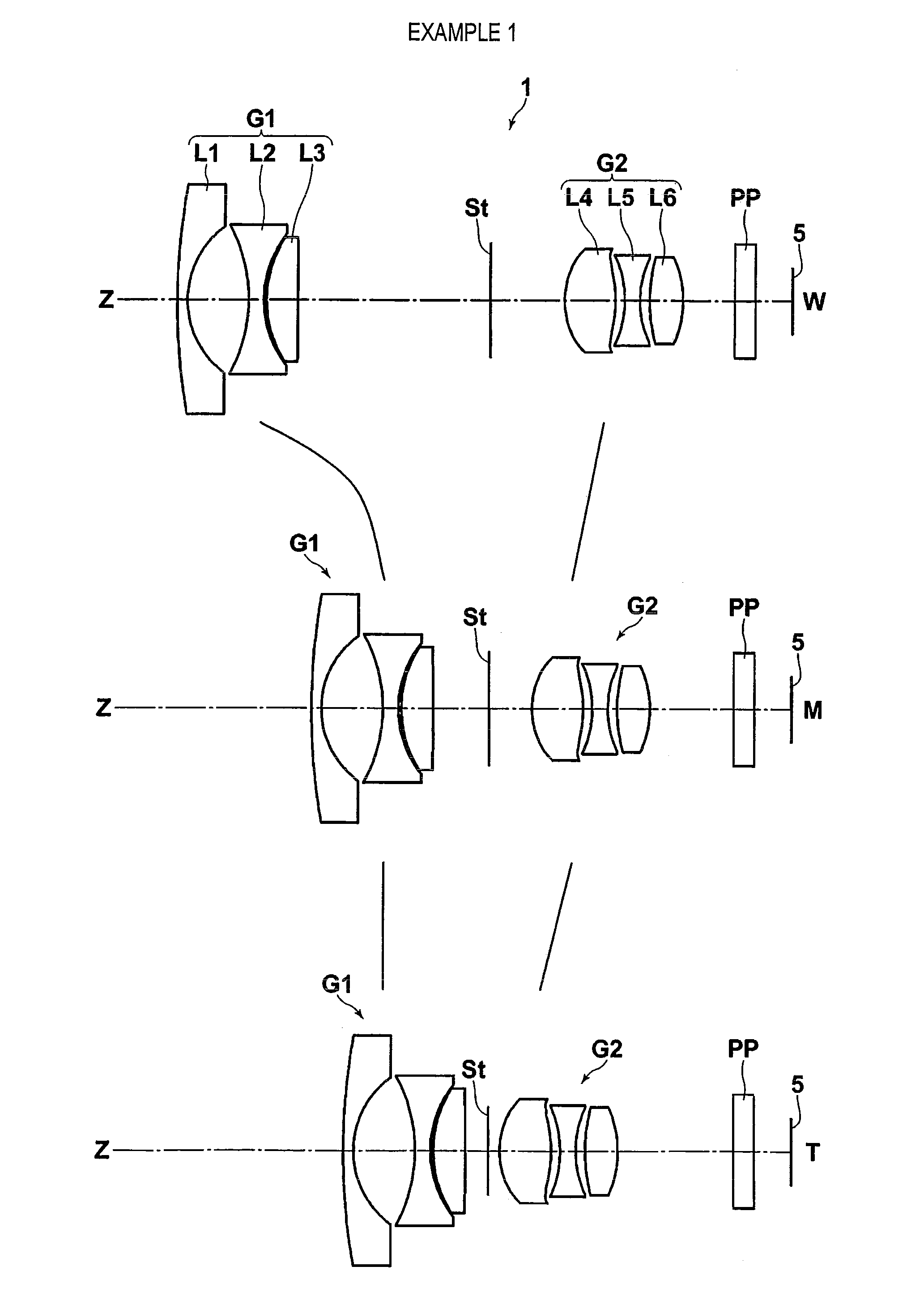
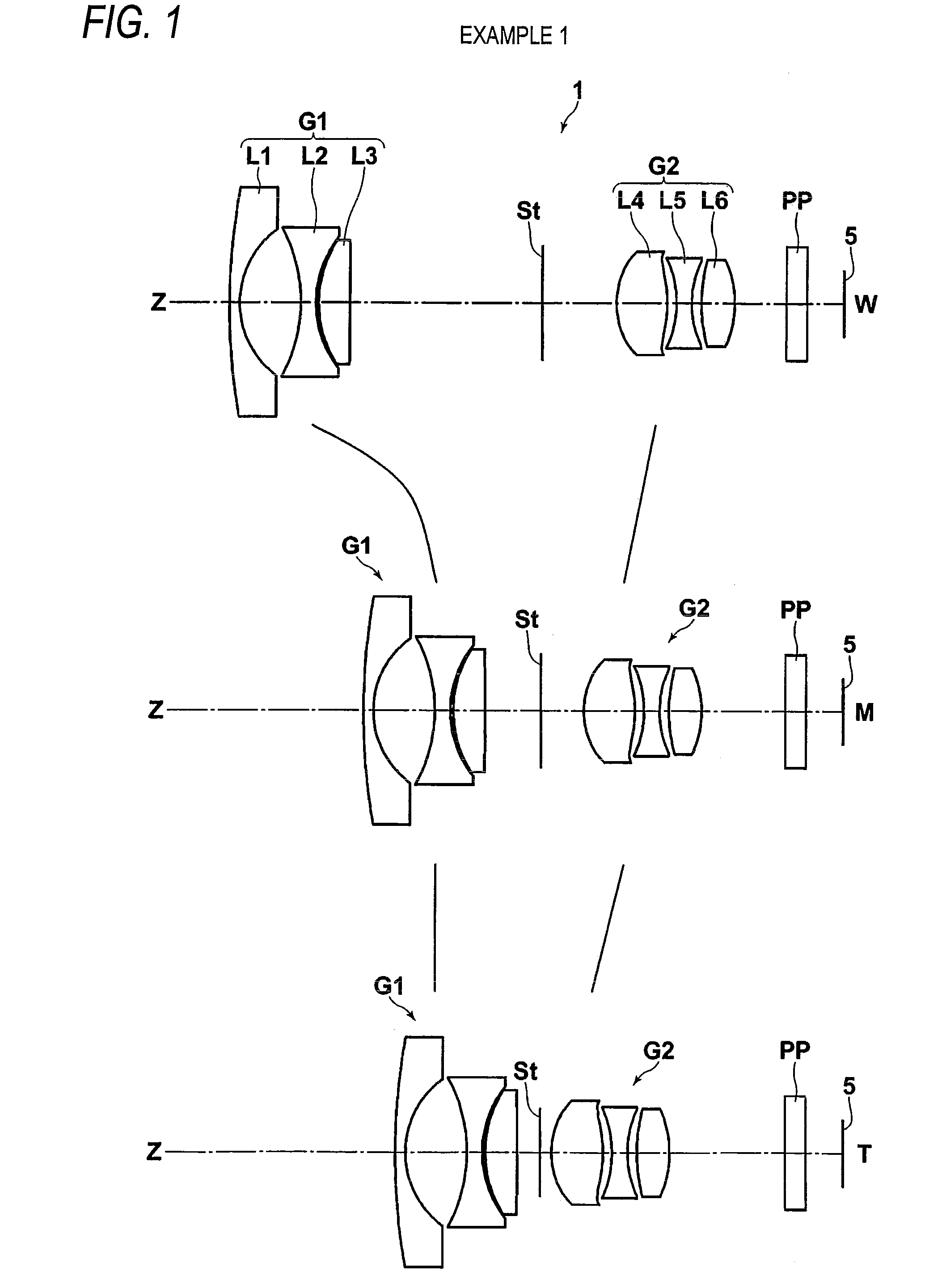
[0058]FIG. 1 shows cross sectional profiles of lenses in a variable power optical system of Example 1. Table 1 shows lens data pertaining to the variable power optical system of Example 1; Table 2 shows aspherical data; Table 3 shows various sets of data; and Table 4 shows data pertaining to temperature changes. Likewise, Tables 5 to 32 show lens data, aspherical data, various sets of data, temperature change data pertaining to variable power optical systems of Examples 2 to 8. Meanings of symbols in the tables are hereunder described by means of taking Example 1 as an example. The same also basically applies to the tables for Examples 2 through 8.

[0059]In relation to the lens data shown in Table 1, a surface number sequentially increases toward the image side while a surface of a constituent element closest to the object side is taken as the first surface, and on-axis surface spacing designates surface spacing between a surface of interest and the next surface along the optical axi...

example 2

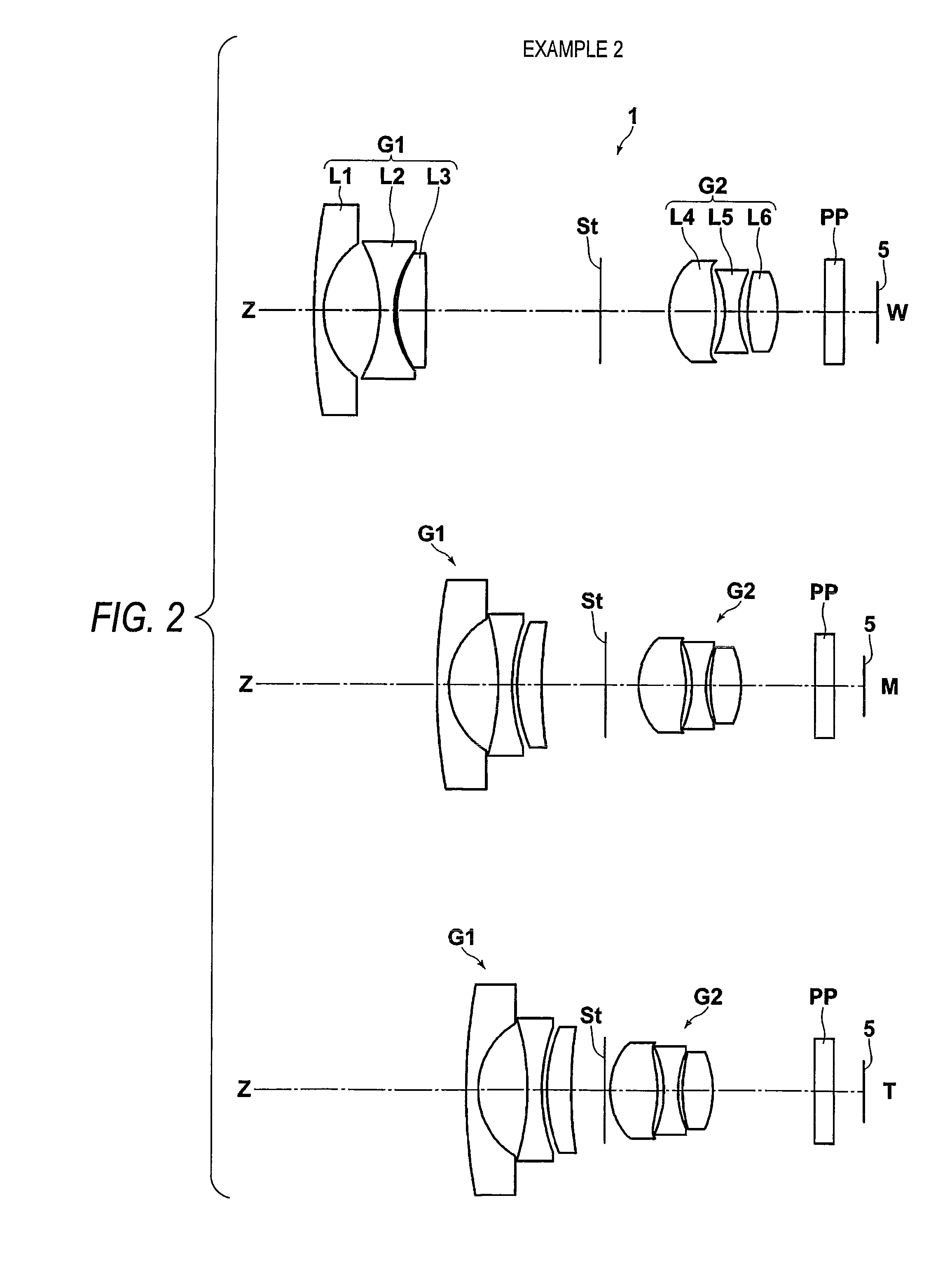
[0073]Table 5 shows lens data pertaining to a variable power optical system of Example 2; Table 6 shows aspherical data; Table 7 shows various data; and Table 8 shows temperature change data. FIG. 2 shows the configuration diagram of a lens (rough paths of movements of respective lens groups are omitted).

[0074]In Example 2, three plastic lenses L2, L4, and L5 are used. An aspherical lens is used for L4. Amounts of displacements of the imaging point obtained through calculation fall within an allowable range in response to a required temperature change of ±35° C., and the field angle achieved at the wide angle end is 126°. Thus, the objective of the invention is accomplished.

[0075]

TABLE 5Example 2Lens dataSurfaceCurvature radiusSurface spacingNdνd161.4821.2821.8040046.628.0635.3141.000003−24.4601.5001.5095956.2418.9730.5341.00000516.5452.6031.9228518.9643.864D6(Variable)1.000007StopD7(Variable)1.00000 8*7.2844.9881.5095956.2 9*−10.9360.6581.0000010 −10.7381.5001.6059526.911 9.9730.49...

example 3

[0079]Table 9 shows lens data pertaining to a variable power optical system of Example 3; Table 10 shows aspherical data; Table 11 shows various data; and Table 12 shows temperature change data. FIG. 3 shows the configuration diagram of a lens (rough paths of movements of respective lens groups are omitted).

[0080]In Example 3, three plastic lenses L2, L4, and L5 are used. An aspherical lens is used for L4. Amounts of displacements of the imaging point obtained through calculation fall within an allowable range in response to a required temperature change of ±35° C., and the field angle achieved at the wide angle end is 121°. Thus, the objective of the invention is accomplished.

[0081]

TABLE 9Example 3Lens dataSurfaceCurvature radiusSurface spacingNdνd130.6241.2821.8040046.627.5595.2981.000003−22.2701.5011.5095956.2414.8290.8021.00000514.7122.6031.9228518.9633.216D6(Variable)1.000007StopD7(Variable)1.00000 8*7.4574.9201.5095956.2 9*−10.2201.3151.0000010 −12.3651.5001.6059526.911 7.7000...


PUM


Abstract

On condition that a first lens group adopts at least one plastic lens; a second lens group adopts at least any two adjacent plastic lenses; the first lens group monotonously moves from an object side to an image plane side in a zooming; the second lens group monotonously moves from the image plane side to the object side; wherein fw / fpi represents a ratio of refractive power of the entire system achieved at a wide angle end to refractive power of the respective lenses; P1 represents a total of fw / fpi of the plastic lenses of the first lens group; and P2 represents a total of fw / fpi of the plastic lenses of the second lens group, the following conditional expressions −0.22<P1<−0.01 and −0.15<P2<−0.03, are both fulfilled.

Description

[0001]The present application claims priority from Japanese Patent Application No. 2008-332068 filed on Dec. 26, 2008 and Japanese Patent Application No. 2009-286246 filed on Dec. 17, 2009, the entire content of which is incorporated herein by reference.BACKGROUND OF INVENTION[0002]1. Field of the Invention[0003]The present invention relates to a viable power optical system used in an onboard camera, a surveillance camera using an imaging element, such as a CCD and a CMOS, and, more particularly, to a variable power optical system suitable for use in a surveillance camera.[0004]2. Description of the Related Art[0005]A variable power optical system employed in a varifocal lens for use with a surveillance camera provides convenience which allows a user to set a focal length and a distance to a subject according to a user environment, and hence a market for the variable power optical system has recently undergone particular expansion as an optical system for use with a surveillance cam...

Claims


Application Information

Patent Timeline
Patent Type & Authority Patents(United States)
IPC IPC(8): G02B15/14
CPCG02B15/177
Inventor OHNO, KAZUNORI
Owner FUJI PHOTO OPTICAL CO LTD
Learn More