Clamping apparatus for a disc player

a technology of disc player and clamping device, which is applied in the direction of magnetic recording, data recording, instruments, etc., can solve the problems of difficult to remove the clamper from the turntable, risk of losing stability in the release operation, and difficult selection of material for the holding lever, so as to achieve the advantage of stably holding the clamper and efficiently removed

Inactive Publication Date: 2011-08-16
TANASHIN DENKI CO
View PDF11 Cites 2 Cited by
  • Summary
  • Abstract
  • Description
  • Claims
  • Application Information

AI Technical Summary

Benefits of technology

[0019]According to the clamping apparatus for a disc player of the present invention, because the clamper is released by a pair of linking mechanisms arranged at both sides of the clamper, there is no need to arrange clamping apparatus components in the entire area around the clamper, and also no particular large components are used to achieve miniaturization. Because the end of the clamper releasing member is designed to scoop the rim of the clamper while forming a circular trajectory when the front linking member and the rear linking member rotate synchronously, the radius of the circular trajectory of the clamper releasing member end can be the same length as the link span of the front and rear linking members. As a result, the clamper releasing member is released substantially outward from the clamper during disc playback, and the clamper can be substantially separated from the turntable during the stop time, and no large components are used, thereby achieving miniaturization and thinning of the apparatus.
[0021]Furthermore, when at least one of either the clamper rim end or the releasing member end which scoops the clamper rim is made to have a tapered surface, the clamper can be separated promptly from the turntable because the operational element in the horizontal direction of the releasing member is converted to the operational element in a direction upward of the clamper, reducing the amount of movement in the upward direction of the clamper releasing member so that further thinning can be achieved, and the advantageous effect of stably holding the clamper can be obtained.
[0022]When the link spans of the front linking member and the rear linking member are nearly the same length and the rotating ends of these linking members are placed nearly directly underneath each of the rotational axes, the end of the releasing member quickly gets closer to the clamper from the outside of the clamper at the beginning of the rotation of the front and rear linking members, and the operational element upward of the releasing member end gradually increases, and the clamper can be efficiently removed from the turntable with a small amount of movement by the clamper releasing member.
[0023]Further, when the link span of the rear linking member is set to be slightly longer than the link span of the front linking member, the clamper releasing member can be inclined so as to make the end which is the clamper side of the clamper releasing member to be higher than the end of the opposite side, strengthening the clamper releasing force by the clamper releasing member.

Problems solved by technology

However, because characteristics of flexibility and strong releasing force are essentially incompatible, it has been difficult to release the clamper from the turntable with a strong force using a holding lever having flexibility.
Consequently, there is the risk of losing stability in the releasing operation, and selection of material for the holding lever is difficult, requiring the use of expensive material.
Consequently, if the clamper releasing member is merely mounted on the frame, a different mechanism would be needed to release substantially outward from the clamper during the playback operation, making miniaturization and thinning extremely difficult.

Method used


Image

  • Clamping apparatus for a disc player
  • Clamping apparatus for a disc player
  • Clamping apparatus for a disc player

Examples


Embodiment Construction

[0051]Preferred Embodiments of the present invention will be described hereafter with reference to drawings.

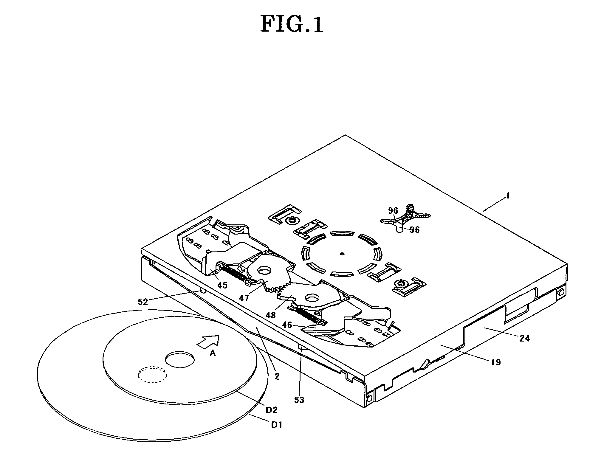
[0052]FIG. 1 is a diagrammatic perspective view showing the exterior of a mechanism unit 1 of a disc player used for automobiles. At the front surface, the mechanism unit 1 of the disc player provides a disc insertion port 2 where a large disc D1 or small disc D2 is inserted and ejected. An arrow A shows the disc insert direction, and the opposite direction indicates the disc eject direction. Together, the disc insert direction and disc eject direction are collectively referred to as the disc insert / eject direction.

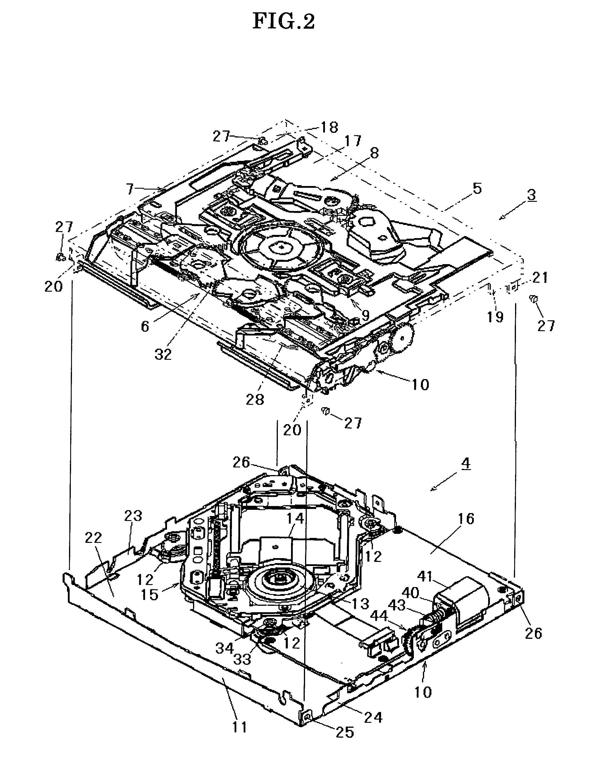
[0053]FIG. 2 is a diagrammatic perspective view showing the mechanism unit 1 of the disc player by breaking out an upper unit 3 and a lower unit 4.

[0054]FIG. 3 shows a top plane view of the upper unit 3; and FIG. 4 shows a top plane view of the lower unit 4.

[0055]The upper unit 3, as shown in FIG. 2 and FIG. 3, comprises an upper frame 5 (shown by a virtual line), a...


PUM

PropertyMeasurementUnit
widthaaaaaaaaaa
inclined angleaaaaaaaaaa
timeaaaaaaaaaa

Abstract

The present invention relates to a clamping apparatus for a disc player which is able to accurately release a clamper from a turntable while improving miniaturization and thinning. The clamping apparatus for the disc player where the turntable and the clamper clamp a disc by magnetic force comprises a clamper releasing means having a pair of linking mechanisms arranged in symmetrical positions across the axial line of the clamper, and each linking mechanism has a front linking member and a rear linking member with the ability to freely rotate with the frame by centering two rotational axes placed on a single flat surface that is orthogonal to the axial line, and a clamper releasing member which is axially supported at each rotating end of the front linking member and the rear linking member; the mutually opposing ends of both clamper releasing members are moved with a circular trajectory by synchronously rotating the front linking member and the rear linking member, and the ends of both clamper releasing members are engaged to the outer periphery of the clamper, releasing the clamper from the turntable.

Description

BACKGROUND OF THE INVENTION[0001]1. Filed of the Invention[0002]The present invention relates to a clamping apparatus for a disc player to replay a CD, DVD, or the like.[0003]2. Description of the Prior Art[0004]There has been demand for miniaturization and thinning in a clamping apparatus for a disc player in which a clamper is arranged between a frame and a turntable; a disc is clamped by the magnetic force by the turntable and the clamper; the clamper releasing means is driven by the driving means; and the clamper is released from the turntable by the clamper releasing means. There are special regulations governing the maximum outer dimensions for in-car disc players with strict dimensional restrictions for integrated clamping apparatuses for automobiles.[0005]Japanese Laid-open patent publication 2002-109803 discloses the following clamping apparatus for devising thinning.[0006]Namely, a clamper is released from a turntable by three latching pieces by arranging three flexible ho...

Claims


Application Information

Patent Timeline
Patent Type & Authority Patents(United States)
IPC IPC(8): G11B17/028G11B17/04
CPCG11B17/0282G11B17/0284G11B17/0404G11B17/0515G11B17/028G11B17/051
Inventor YAMANAKA, TAKASHI
Owner TANASHIN DENKI CO
Why Eureka
Try Eureka