Lighting device

A lighting device and installation part technology, which can be applied to lighting devices, fixed lighting devices, components of lighting devices, etc., can solve problems such as the increase of inspection equipment costs, and achieve the effect of simplifying structure and realizing miniaturization.

Inactive Publication Date: 2005-10-05
KYOTO DENKIKI KK
View PDF1 Cites 0 Cited by
  • Summary
  • Abstract
  • Description
  • Claims
  • Application Information

AI Technical Summary

Problems solved by technology

Therefore, it is necessary to prepare lighting devices with required irradiation angles according to the size (height) of the object to be inspected, which raises the problem that the cost of inspection equipment increases.

Method used


Image

  • Lighting device
  • Lighting device
  • Lighting device

Examples


Embodiment Construction

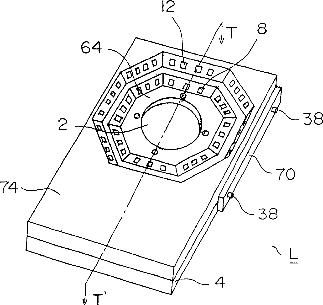
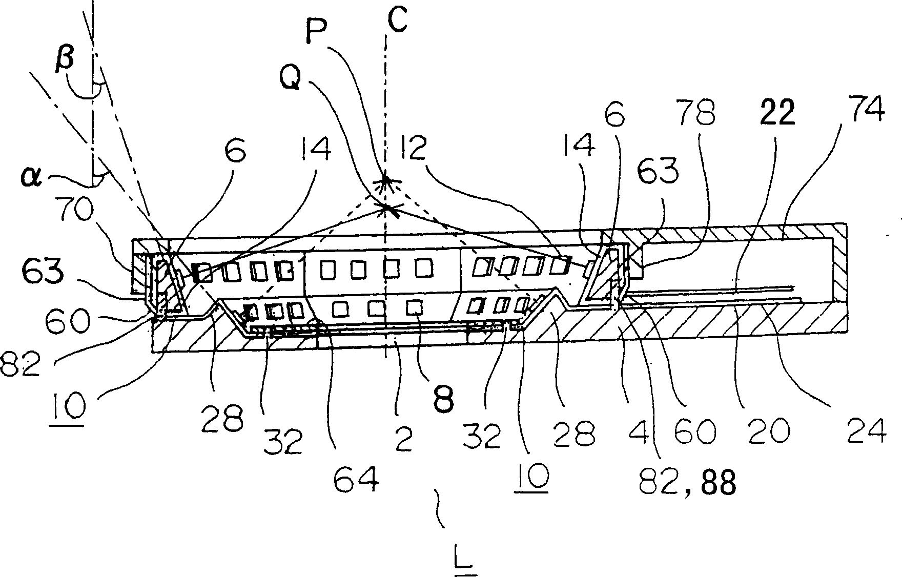
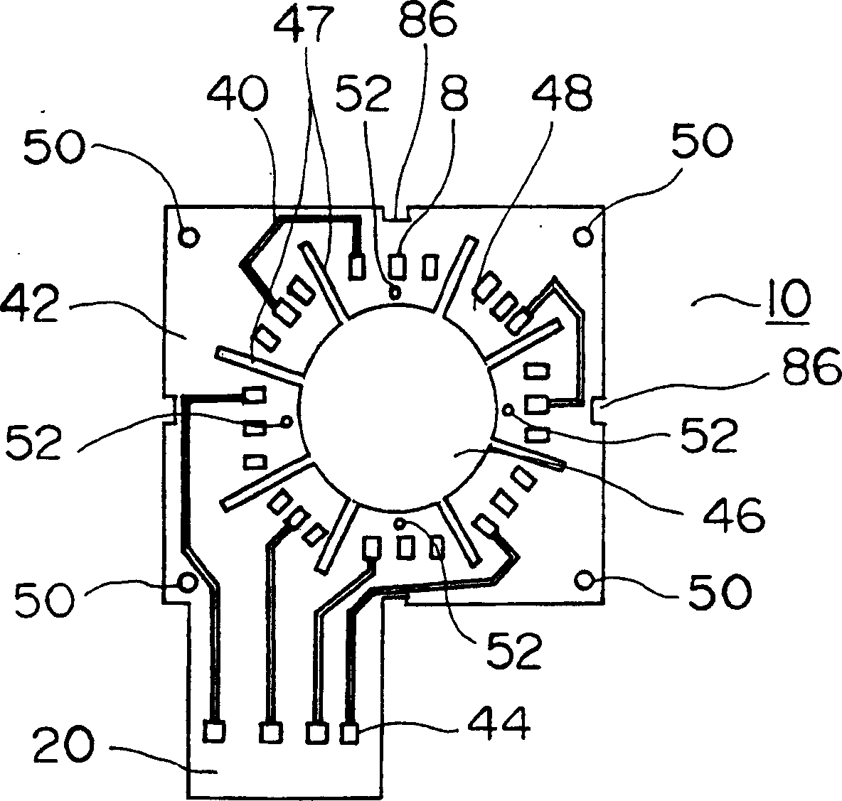
[0036] Hereinafter, one embodiment of the lighting device according to the present invention will be specifically described with reference to the drawings.

[0037] figure 1 is a perspective view showing the lighting device of the present invention, figure 2 yes figure 1 The cross-sectional view of the T-T' line in the middle, image 3 is a plan view showing the first sheet-shaped substrate, Figure 4 is a plan view showing the second sheet-shaped substrate, Figure 5 is an exploded perspective view illustrating a method of fixing the first sheet-shaped substrate to the first housing member, Figure 6 It is an exploded perspective view for explaining the method of fixing the second sheet-shaped substrate to the second housing member, and FIG. 7 is a cross-sectional view showing a state in which the second sheet-shaped substrate is mounted on the second housing member, Figure 8 It is a bottom view showing the state where the second sheet-shaped substrate is mounted on th...


PUM


Abstract

This invention provides a lighting device whereby alignment for mounting a sheet board onto a case member can easily and accurately be carried out. The lighting device includes a first case member 4, a second case member 6 mounted on the first case member, a first sheet board 10 provided with a plurality of first light emitting elements 8, a second sheet board 14 provided with a plurality of second light emitting elements 12, and a first retaining member 64 fitted to the first case member to fix the first sheet board. The first sheet board includes a lighting region to which a plurality of the first light emitting elements and a wiring pattern connected electrically to them are arranged, and a terminal region 22 provided with a terminal 44 electrically connected to an external power supply. The outer circumference of the lighting region of the first sheet board is fixed between the first and second case members and the inner circumference of the lighting region is fixed between the first case member and the first retaining member.

Description

technical field [0001] The present invention relates to a lighting device used for inspection of products, etc., for example in a factory. Background technique [0002] For a long time, when inspecting the quality of industrial products such as printed circuit boards and semiconductors on the production line, such as poor soldering, defects, adhesion of foreign matter, etc., or printing errors such as the date of manufacture on food cans, it has been photographed by a CCD camera, etc. The image is subjected to image processing inspection. In this image processing inspection, a specific part of the component is photographed, and the presence or absence of abnormality is checked by comparing the imaging result of a normal component. In this image processing inspection, it is necessary to illuminate the portion of the inspection object captured by the CCD camera, and as an illumination device used for the above work, for example, a ring illumination device or the like is used....

Claims


Application Information

Patent Timeline
Patent Type & Authority Applications(China)
IPC IPC(8): F21V19/00F21S2/00F21S8/04F21Y101/02G01B11/00G01N21/84H01L33/62
CPCF21K9/23F21S2/005F21V15/01F21V19/001F21W2131/411F21Y2107/40G01N2021/8816
Inventor 日野隆志法贵繁
Owner KYOTO DENKIKI KK
Why Eureka
Try Eureka