
Speed and resistance apparatus

a technology of resistance apparatus and speed, applied in the field of speed resistance apparatus, can solve the problems of negative and deleterious fatigue effect, failure to obtain, all kinds of poor habits, etc., and achieve the effect of maximizing this aerodynamically centralized alignment and highly decreasing lateral displacemen

Inactive Publication Date: 2011-08-16
WROCLAWSKY SOL
View PDF23 Cites 11 Cited by
  • Summary
  • Abstract
  • Description
  • Claims
  • Application Information

AI Technical Summary

Benefits of technology

[0011]Other objects of the invention are to provide a measurement system which also includes resistance inducing attachments tethered to a training athlete and also aerodynamically stabilized so as to minimize any interference in the course of the exercise.
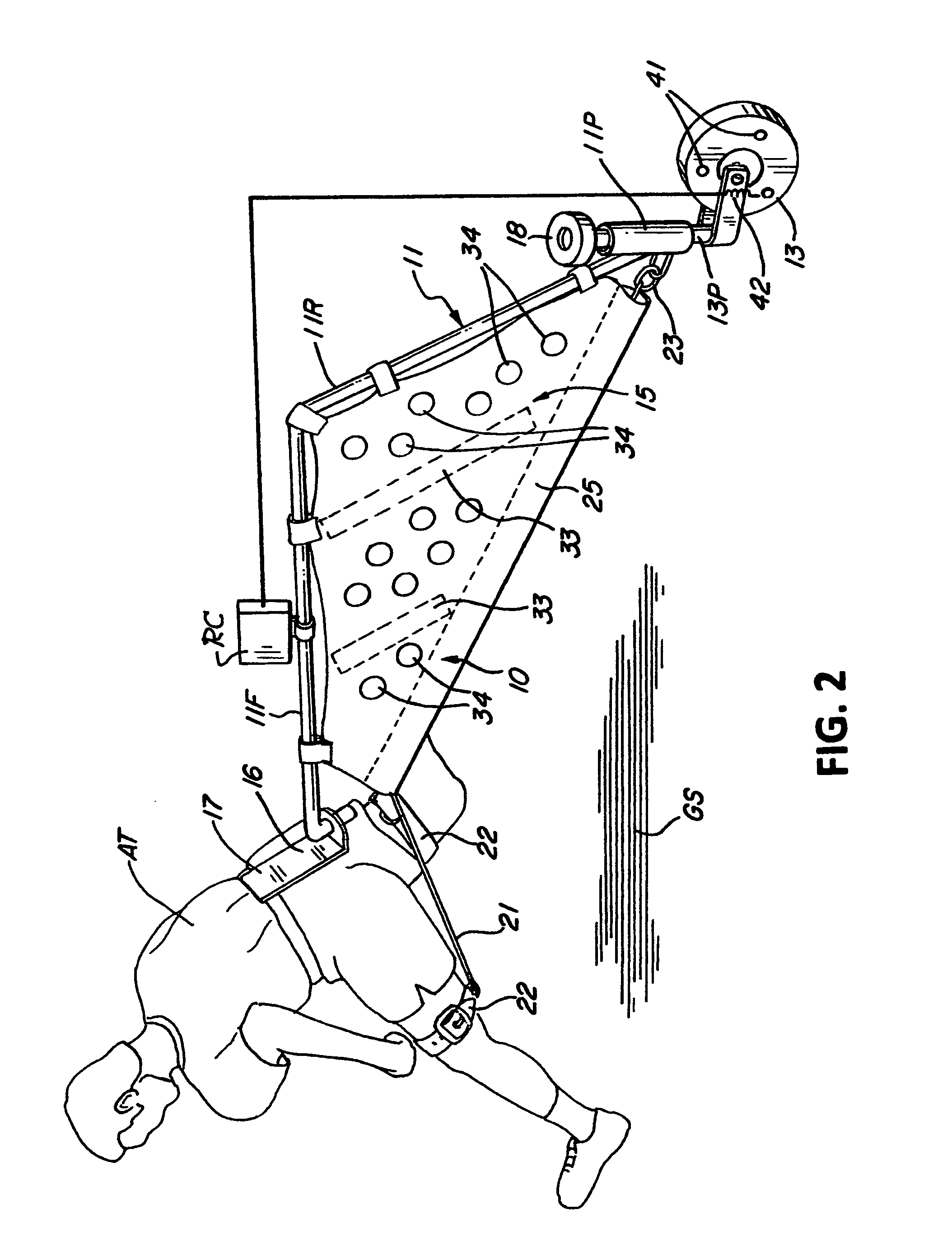
[0014]A dimensionally conformed generally triangular fabric panel is then secured at two of its edges to the respective frame pieces with the third edge once again folded over to form an envelope or sheath through which an elastomeric band is stretched from the trailing end of the frame to a split harness having its ends respectively secured to the athlete's thighs. Preferably the dimensions of the frame and the included angle between its pieces are each selected such that the ground contact of the trailing wheel assembly is spaced behind the athlete's concurrent foot prints on the ground, thereby insuring a generally centered alignment of the frame behind the athlete.
[0015]To maximize this aerodynamically centralized alignment behind the athlete while he or she is moving down the track, the trailing fabric panel in the instant invention is both perforated by a plurality of openings and is also stretched to its full planform by ribs or battens that extend to its folded over free edge within which the elastomeric restraint band is stretched. Thus in the course of each of the athlete's strides a substantial fabric area is laterally moved in coordination with the leg movement that is aerodynamically attenuated towards the trailing end, resulting in a highly decreased lateral displacement of the trailing wheel assembly to thereby keep it generally centered on the course or track. The relative dimensions along with this centering tendency and the generally triangular planform result in a mechanism that presents little interference to the athlete while insuring a running leg motion that has minimal lateral components.

Problems solved by technology

Those engaged in the training of athletes for sporting endeavors that entail complex body movements may recognize the negative and deleterious effect of fatigue on the efficacy of the training program.
Simply, the course of training by sheer repetition of complex or changing movements often fails to obtain the expected result since the onset of fatigue in a muscular grouping is rarely uniform and the imperceptible fatigued muscle compensation then results in all sorts of poor habits.
This is particularly pronounced amongst the more competitive athletes that by their dedication are constantly working out since most current exercise facilities favor just one or another large muscle group that results in an uneven muscular development in which the smaller ones are deferred to inattention.
When strained by repetitive training these transient movement patterns include smaller muscles then invariably tire at a faster rate, resulting in compensatory changes which grossly distort the efficacy of further repetition, to a point where continued training may simply induce improper habits that produce a negative, rather than a positive, result.
Unlike this coordinated development path where the exercise focus is easily determined by the total time needed to reach a finish line, the dynamics of a sudden lunge out of the starting blocks, for example, present a more difficult analytic assessment.
While one may choose a point on the track to somehow quantify these transient, such a measurement alone is simply insufficient as it often hides negative habits that often manifest themselves only much further along the track.
While quite useful in inducing added effort during a steady state treadmill driven exercise, this combination provides little information, and thus little training utility, useful in the development of transient capabilities like those during all the movement patterns from the starting blocks to the finish.

Method used


Image

  • Speed and resistance apparatus
  • Speed and resistance apparatus
  • Speed and resistance apparatus

Examples


Embodiment Construction

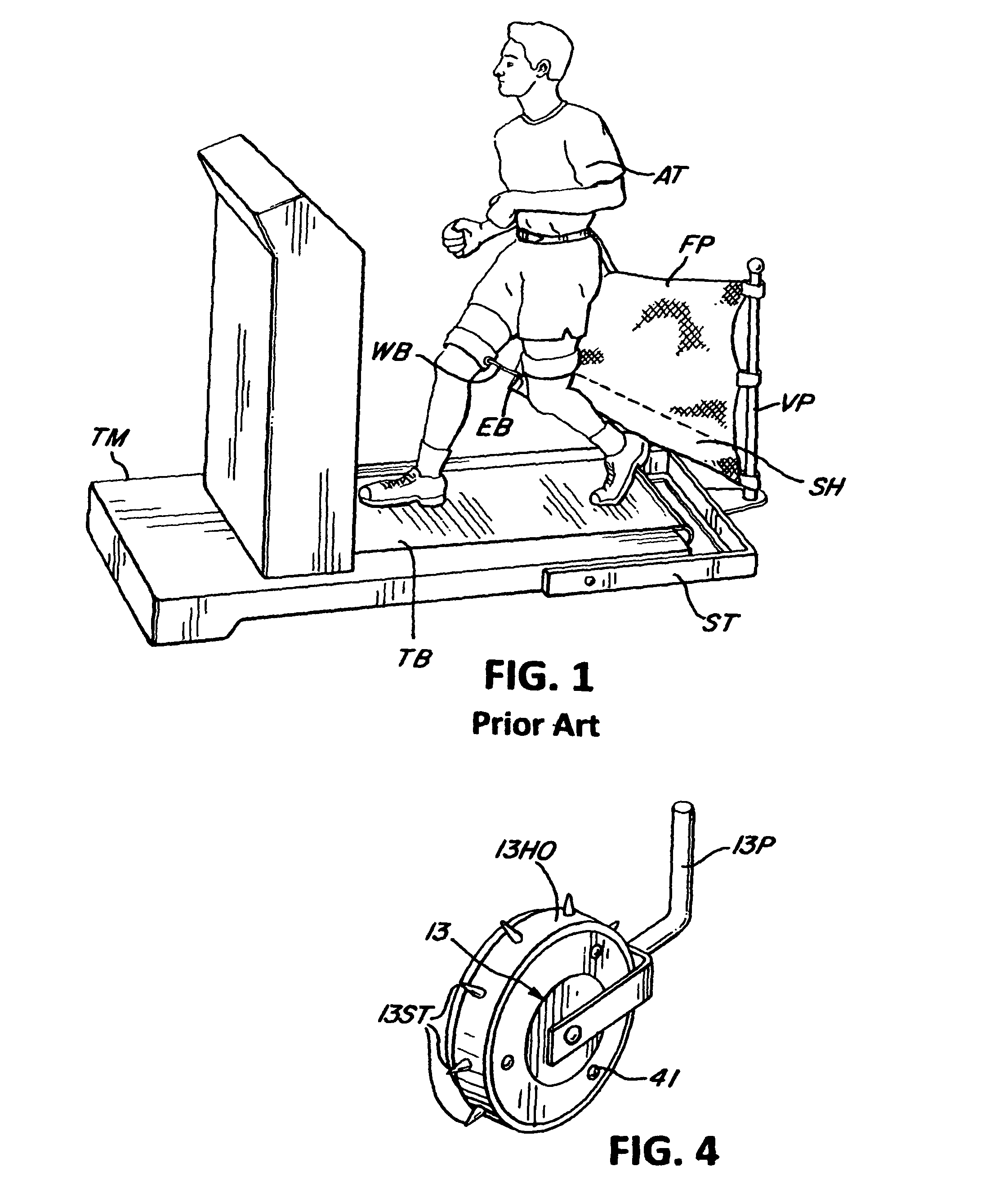
[0021]In my prior U.S. Pat. No. 6,652,427 issued to me on Nov. 25, 2003, I have described a treadmill resistance apparatus, which I now generally summarize by reference to FIG. 1 captioned as ‘PRIOR ART’ describing a structure ST attachable at the rear of a treadmill TM to deploy a vertical post VP behind the end of the treadmill belt TB. One edge of a fabric panel FP, tethered at the other edge from the waist of an athlete or user AT training on the treadmill, is attached to the post to suspend a folded lower edge sheath or pocket SH in which an elastomeric band EB is stretched from the base of the post to a split harness or webbing WB secured to the athlete's thighs. In this form a restraining load is applied to the legs of the athlete as he or she are training on the treadmill with resulting lateral movement of the load tethering mechanism delayed by the aerodynamic loads on the fabric panel to delay the lateral shift of the tethered structure in order to insure clearance for the...


PUM


Abstract

A rolling resistance producing apparatus is tethered to trail behind a person includes a longitudinally aligned fabric panel stretched on a frame which also engages the rear end of an elastomeric band that is stretched through a sheath formed in the panel to engage a harness tied to selected limbs of the person to provide resistance thereto. The trailing end of the frame is supported on a wheel to follow the person as she or he are moving. A measurement system sensing the movement of the wheel then records the rate of the movement to provide an indication of fatigue.

Description

REFERENCE TO RELATED APPLICATIONS[0001]This application obtains the benefit of the earlier filing date of U.S. Provisional Application Ser. No. 61 / 213,536 filed on Jun. 18, 2009.BACKGROUND OF THE INVENTION[0002]1. Field of the Invention[0003]The present invention relates to an apparatus for providing resistance to the legs of an athlete while training to improve sudden movement, along with a measurement record thereof, and more particularly to a resistance and measurement system conformed to align behind the athlete during his or her accelerating movement.[0004]2. Description of the Prior Art[0005]Those engaged in the training of athletes for sporting endeavors that entail complex body movements may recognize the negative and deleterious effect of fatigue on the efficacy of the training program. Simply, the course of training by sheer repetition of complex or changing movements often fails to obtain the expected result since the onset of fatigue in a muscular grouping is rarely unif...

Claims


Application Information

Patent Timeline
Patent Type & Authority Patents(United States)
IPC IPC(8): A63B22/00
CPCA63B21/1419A63B69/0028A63B23/047A63B2220/40A63B21/4009
Inventor WROCLAWSKY, SOL
Owner WROCLAWSKY SOL
Learn More