
Wood working machine

a technology of working machine and woodworking machine, which is applied in the field of woodworking machine and jig, can solve the problems of prior art woodworking machine and process deficiency, inability to fabricate precisely fitting joints without the aid of templates or manufactured patterns, and achieve the effect of reducing the workload

Inactive Publication Date: 2011-08-16
STEPP LEWIS E
View PDF23 Cites 9 Cited by
  • Summary
  • Abstract
  • Description
  • Claims
  • Application Information

AI Technical Summary

Benefits of technology

[0020]A wood working machine structured according to any embodiment of the invention overcomes many limitations characteristic of prior art machines. For example, a machine of the invention can use substantially any size cutting (router) bit, can accommodate a large range of wood thicknesses at substantially any length, and can accommodate dovetail cutting operations for any number of pins at any spacing. The machine can be wall mounted for convenience of access and operation and for economy of workspace.

Problems solved by technology

However, a deficiency in prior art woodworking machines and processes has resided in the inability to fabricate precisely fitting joints without the aid of templates or manufactured patterns, particularly of the dovetail type.

Method used


Image

  • Wood working machine
  • Wood working machine
  • Wood working machine

Examples


Embodiment Construction

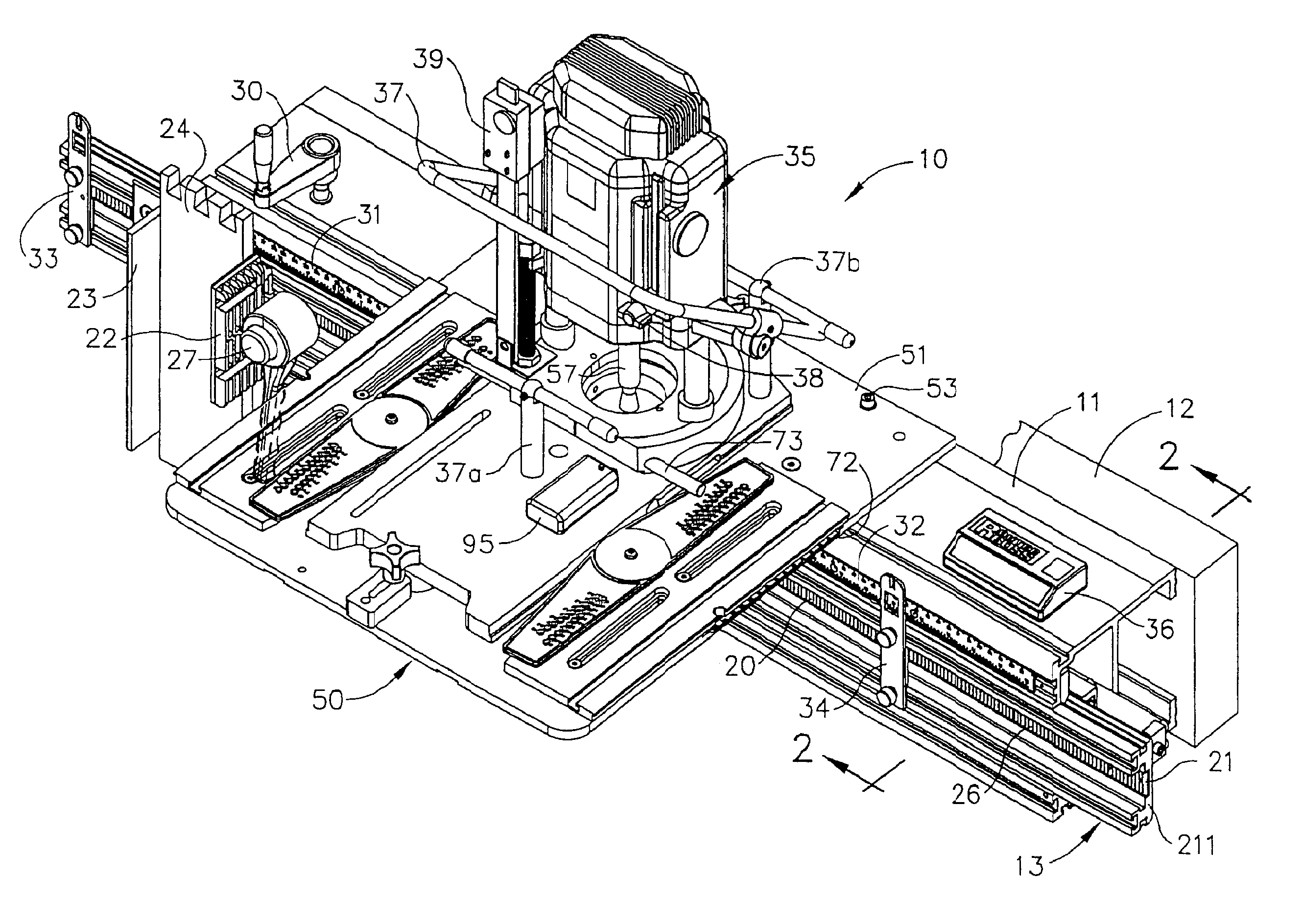
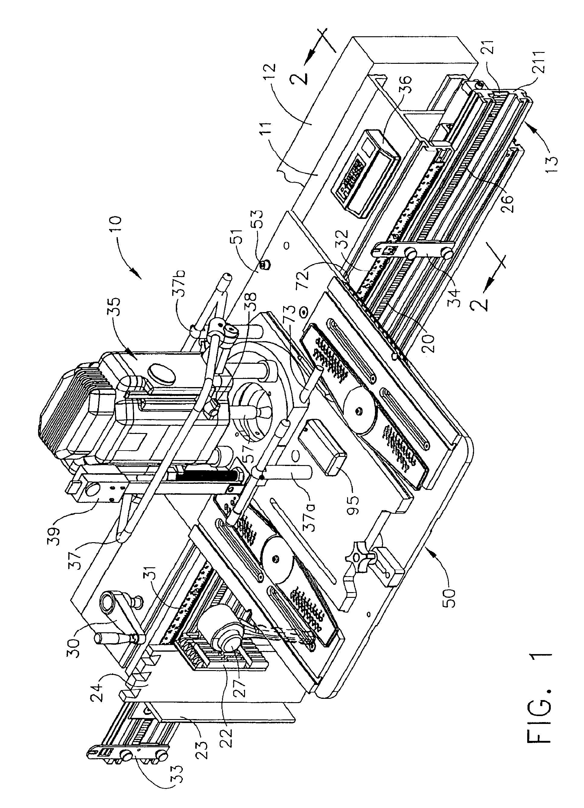
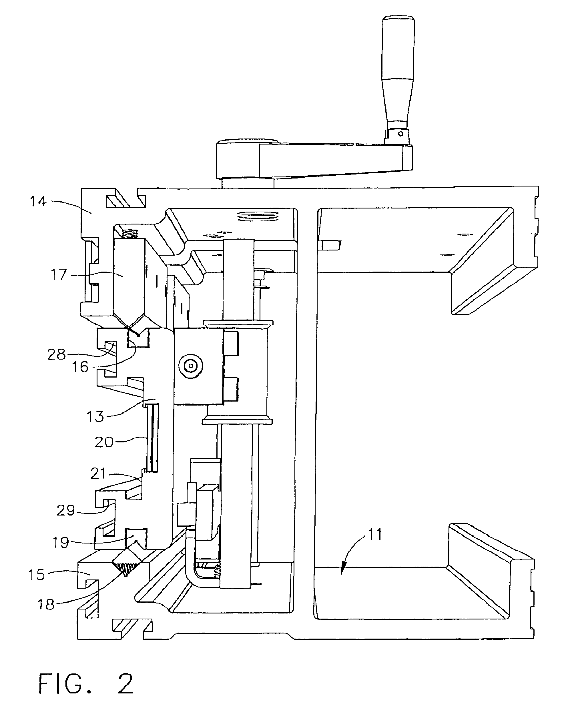
[0036]Referring now to the drawings, FIG. 1 shows a perspective view of one woodworking machine 10 arrangement incorporating elements according to the invention. The machine 10 arrangement shown in FIG. 1 is particularly suited for cutting the dovetail pins and sockets in the fabrication of dovetail joints for making cabinetry or the like. Machine 10 includes a carriage support in the form of a heavy aluminum CNC (Computer Numerically Controlled) machined extrusion 11 that can be attachable conventionally to a shop table (not shown) or to means such as in the form of a wood beam 12 attachable to a wall in such as a shop area. A movable carrier in the form of sliding bar carrier 13 is slidably supported between two flanges of extrusion 11 as depicted more clearly in FIG. 2 that shows an enlarged view in cross section as viewed along lines 2-2 of the machine 10 of FIG. 1. FIG. 2 shows the detail of the structure of the support extrusion 11 and sliding bar carrier 13 supported thereon....


PUM


Abstract

A wood working machine includes a mounting plate assembly for supporting a cutting tool, the assembly including a base plate, first and second intermediate plates on the base plate, and first and second guide plate elements pivotally supported on the intermediate plates, and a cutting tool support plate slidably disposed between the guide plate elements, the guide plate elements being positionable at angular intervals with respect to the intermediate plates, whereby the cutting tool support plate is slidably movable on the base plate between the guide plate elements at a prescribed angle. The mounting plate assembly may include laser sources providing crossed laser beams for positioning the tool bit of the cutting tool near a work piece, and light sources for illuminating the tool bit. A digital sensor may be included for positioning of the work piece.

Description

CROSS-REFERENCE TO RELATED APPLICATIONS[0001]This application claims the benefit of co-pending U.S. Provisional Application No. 61 / 024,716, filed Jan. 30, 2008, and 61 / 089,596, filed Aug. 18, 2008.FIELD OF THE INVENTION[0002]This invention relates generally to woodworking machines, jigs and related woodworking tools, and more particularly to a versatile wood working machine for precisely cutting dovetail joints, mortises, tenons, box joints, raised panels and other joint configurations without the limitations and expense of manufactured templates. The invention also relates to and in performing other wood working procedures in the fabrication of cabinetry or other structures comprising wood.BACKGROUND OF THE INVENTION[0003]In the fabrication of cabinetry, furniture, shelving and other objects of wood, the joining of individual wood pieces using dovetail or box joints, and joints using mortise and tenon, and related joints is in common practice. Existing woodworking machines may incl...

Claims


Application Information

Patent Timeline
Patent Type & Authority Patents(United States)
IPC IPC(8): B27M1/00B27C5/00
CPCB27F1/08B27F1/12B27F1/14Y10T83/855
Inventor STEPP, LEWIS E.
Owner STEPP LEWIS E
Learn More