Logic gate with a reduced number of switches, especially for applications in integrated circuits

a logic gate and switch technology, applied in logic circuits, logic circuits, logic functions, etc., can solve the problems of reducing noise margins, affecting the performance of logic gates, and affecting the quality of logic gates, etc., to achieve low delay propagation times, high reliability, and easy to provide

Inactive Publication Date: 2011-08-09
FABIO ALESSIO NARINO
View PDF6 Cites 1 Cited by
  • Summary
  • Abstract
  • Description
  • Claims
  • Application Information

AI Technical Summary

Benefits of technology

[0017]Another object of the invention is to provide a logic gate structure which have low delay propagation times and independent from the Boolean function implemented by the gate in witch the logic is applied.
[0018]Not last goal of the invention is to provide a logic gate structure which is highly reliable, relatively easy to provide and at competitive costs.

Problems solved by technology

Although the Complementary CMOS logic allows to have output logical levels of 0V e VDD (supply voltage) and wide noise margins and static power dissipation almost null, there are however disadvantages, such as the number of transistor required to implement a single gate is very high (2N MOSFET for a N fan-in logic gate), the propagation delay deteriorates rapidly as a function of the fan-in, big intrinsic capacitances whether incoming or outgoing are present.
However, as consequence of the transistors reduction we have a low logical level that is different from 0V, the noise margins decrease and the static power dissipation become quite big.
However, the logic pass-transistor suffers of some drawbacks, including the high logical level is different from the supply voltage and the output of a gate realized through pass-transistor logic cannot drive the gate terminal of a MOSFET, the connection in series of pass-transistor logical gates is limited because this kind of gate does not enjoy the regenerative property; furthermore every gate needs also of some denied inputs.
Furthermore, the dynamic logic with pre-charge is very sensitive to the capacitive couplings, because they can alter the output value “during the evaluation phase”.

Method used


Image

  • Logic gate with a reduced number of switches, especially for applications in integrated circuits
  • Logic gate with a reduced number of switches, especially for applications in integrated circuits
  • Logic gate with a reduced number of switches, especially for applications in integrated circuits

Examples


Embodiment Construction

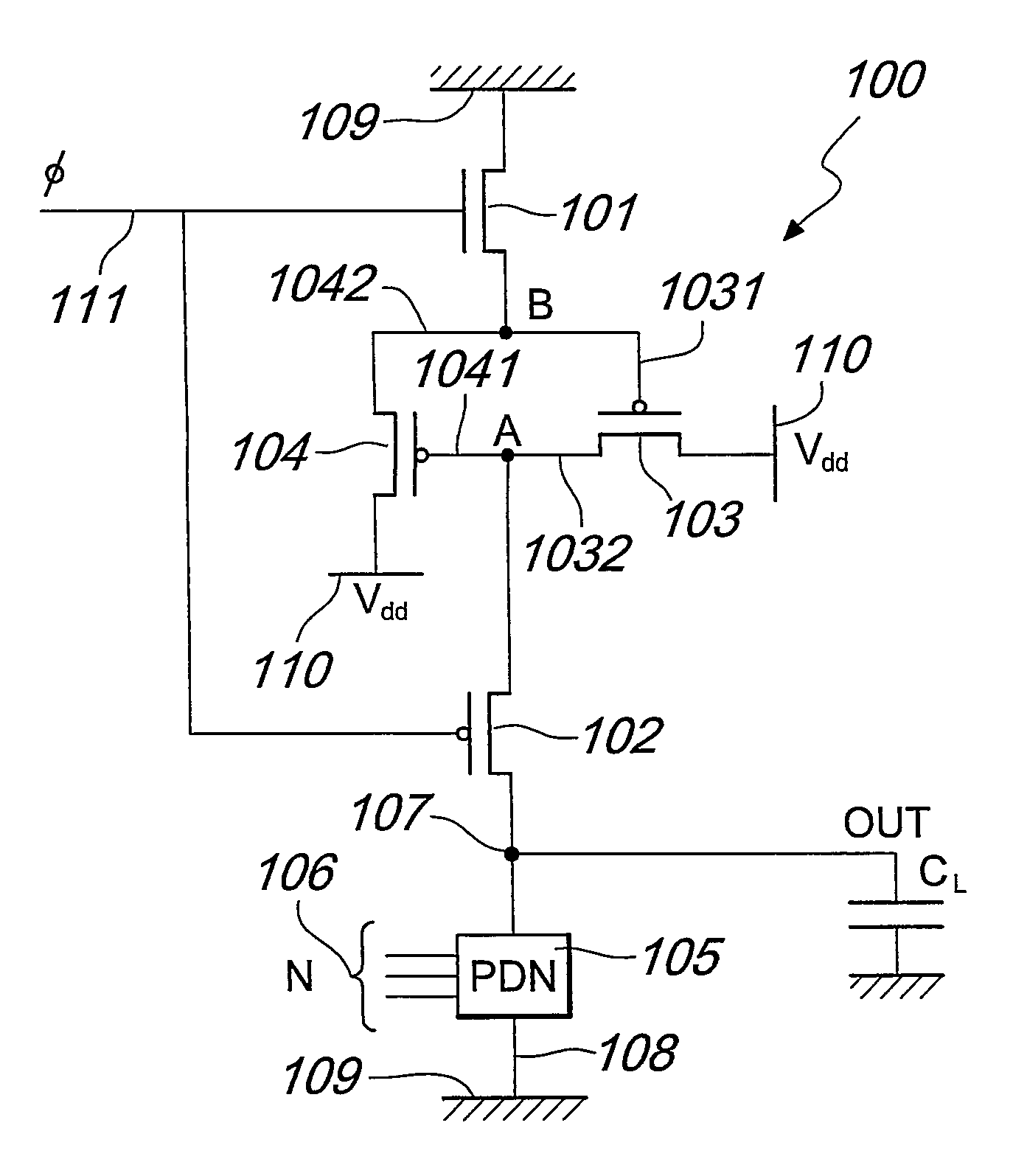
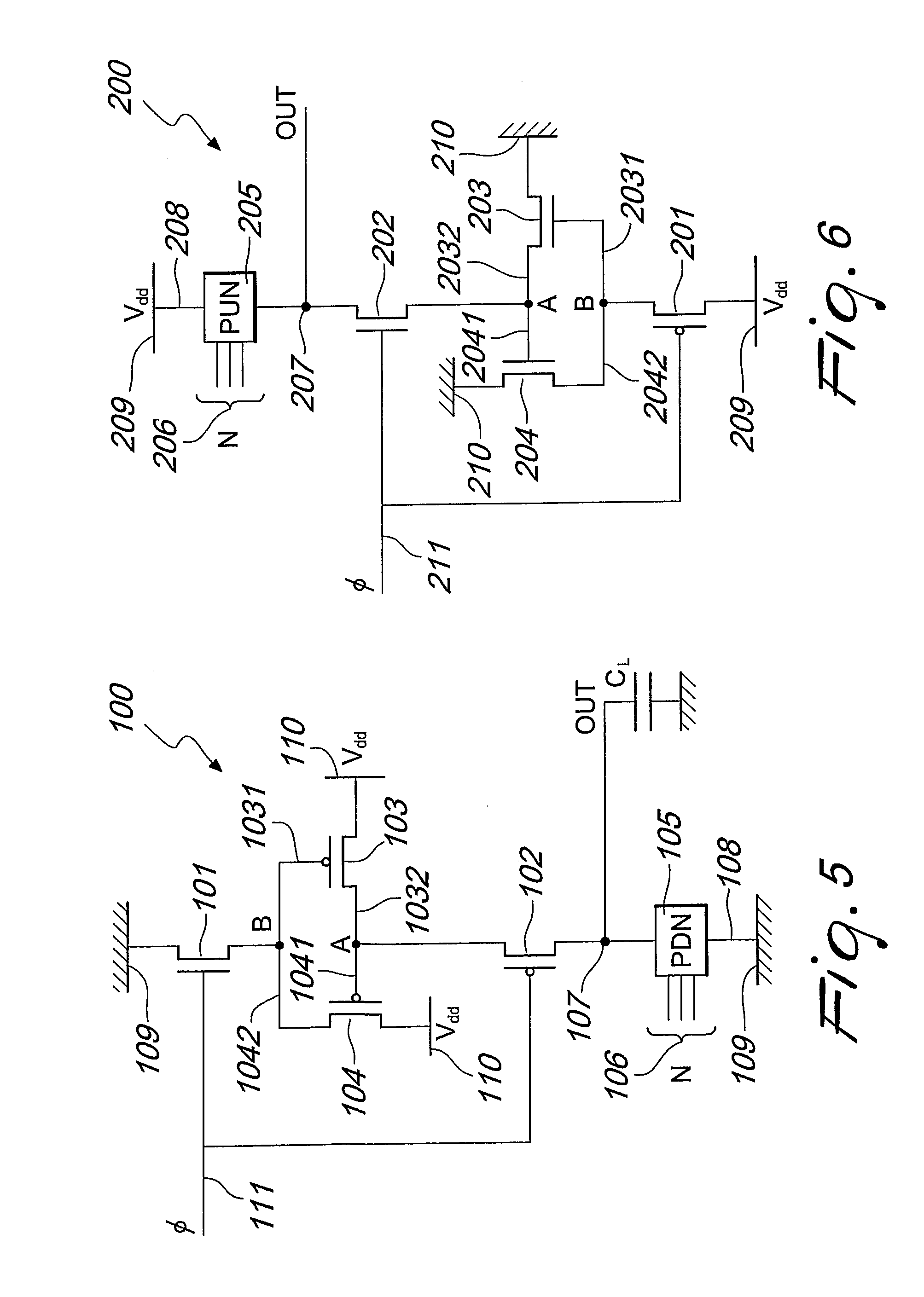
[0034]With reference to the previous figures, the logic gate according to the invention, indicated globally with the reference number 100 or 200, according to whether version we are talking about: with pull-down or pull-up Boolean network, includes a Boolean network or combinational 105, 205 with at least one input 106, 206 (for example, N inputs) and at least a output node 107, 207 and at least a terminal 108, 208 connected to a first node at fixed potential 109, 209 corresponding to a logic level of the logic gate.

[0035]In the case of the logic gate 100, illustrated in FIG. 5, the Boolean network 105 is a pull-down network or a network formed by only n-channel field effect transistors, and the first node at fixed potential 109 is the ground, i.e. the low logical level. In the logic gate 200, illustrated in FIG. 6, the Boolean network 205 is a pull-up network or a network formed by only p-channel field effect transistors, and the first node at the fixed potential 209 corresponds to...


PUM


Abstract

Logic Gate (100), particularly for integrated circuits including a Boolean network (105) having at least an input (106) and having at least an output node (107) and at least a terminal (108) connected to a first node at fixed potential (109) corresponding to a first logical level of the gate. The gate is characterized by the fact that the output node (107) is connected to a first pair of switches including a first switch (101) and a second switch (102), which are activated alternately, and are connected respectively, by a respective terminal, to the first node (109) at fixed potential and to the output node (107). Between the two switches there is a second pair of switches (103, 104) connected to a second node at fixed potential (110) corresponding to a second logical level of the gate. The switches of the second pair of switches are connected together in a way that the turning on of one switch of the second pair involves the turning off of the other switch of the second pair and the turning on of one of the switches of the second pair is suitable to bring the output node (107) to the potential of the second node at fixed potential (110).

Description

TECHNICAL FIELD[0001]The present invention relates to a logic gate with a reduced number of switches, especially for applications in integrated circuits.BACKGROUND ART[0002]Nowadays the realization of integrated circuits (IC) to high performances provides the use of digital structures in CMOS (Complementary Metal Oxide Semiconductor) technology.[0003]In fact, such structures allow obtaining low power dissipation, high speeds and a considerable saving of area on chip.[0004]All digital systems base the most of their working on combinational logic circuits, that is circuits having the property that at any point in time, the output of the circuit is related to its current input signals by some Boolean expression.[0005]There are numerous circuit styles to implement a given logic function, each of which presents advantages and disadvantages, which mark it from the others.[0006]These logic families can be divided mainly into two categories: static logic families and dynamic logic families....

Claims


Application Information

Patent Timeline
Patent Type & Authority Patents(United States)
IPC IPC(8): H03K19/094H03K19/20
CPCG06F7/5016H03K19/0963
Inventor MARINO, FABIO ALESSIOPACCAGNELLA, ALESSANDRO
Owner FABIO ALESSIO NARINO
Why Eureka
Try Eureka