
System and method for use of nanoparticles in imaging and temperature measurement

a technology of nanoparticles and temperature measurement, applied in the field of noninvasive imaging of magnetic particles, can solve problems such as impracticality in arrangement, and achieve the effects of improving sensitivity, speeding up or improving the signal-to-noise ratio of imaging, and improving the sensitivity and localization capabilities of magnetic particle imaging (mpi)

Active Publication Date: 2011-08-09
DARTMOUTH HITCHCOCK CLINIC
View PDF13 Cites 14 Cited by
  • Summary
  • Abstract
  • Description
  • Claims
  • Application Information

AI Technical Summary

Benefits of technology

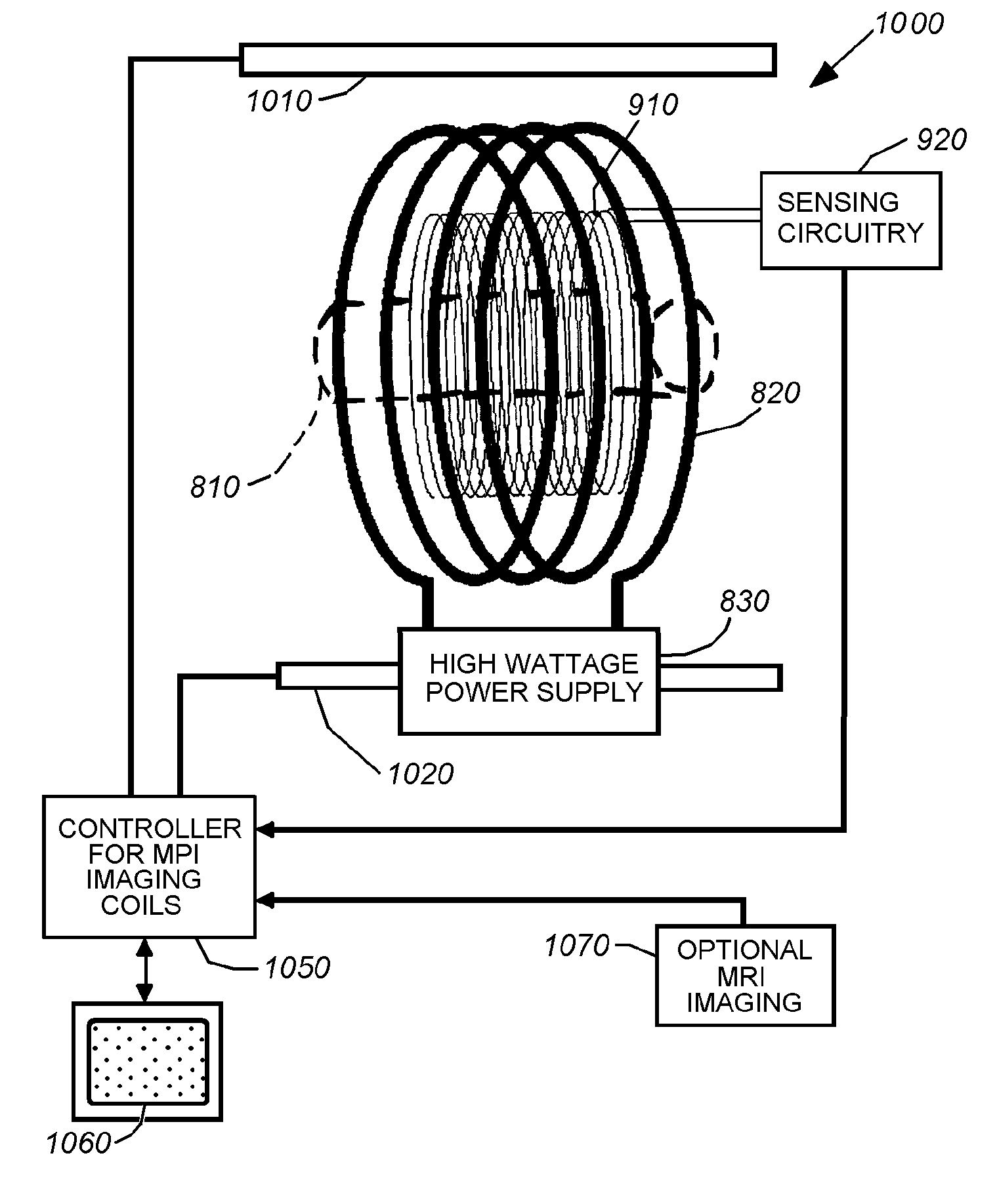
"This patent describes a system and method for improving the sensitivity and localization capabilities of Magnetic Particle Imaging (MPI) by using combinations of static and oscillating magnetic fields. This approach can distribute the signals from the magnetic particles among the harmonics in a specific way to improve the signal-to-noise ratio and speed up imaging. The system can also use the harmonics to provide localization information and enable the use of smaller gradients or saturation fields. The invention can be used in combination with other modalities like MRI to provide a more complete picture of the anatomy of a subject. The method can also be used to measure the temperature of particles in a sample and monitor the binding energy of the particles. Overall, this invention provides a more effective and accurate way to image and locate magnetic particles in a sample."

Problems solved by technology

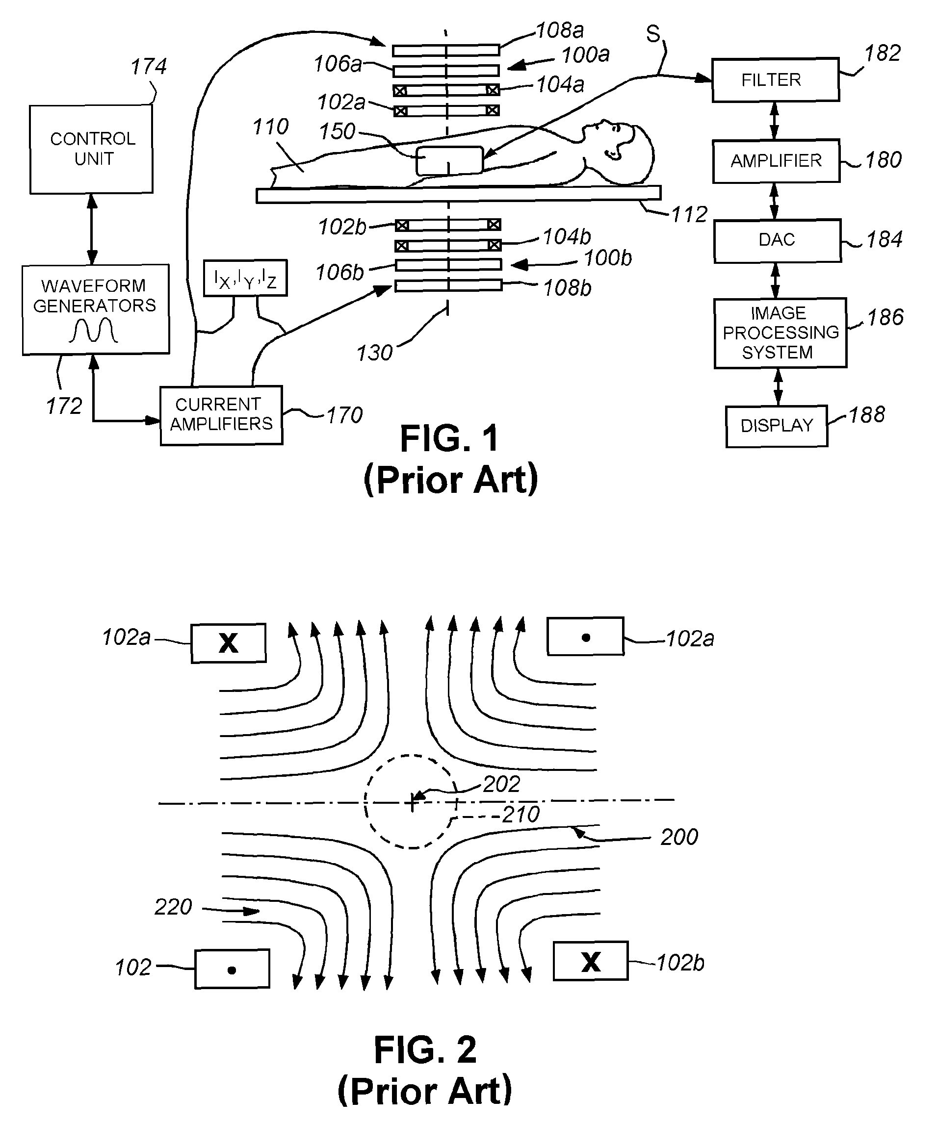
This arrangement may be impractical, as it impeded access to the examination area.

Method used


Image

  • System and method for use of nanoparticles in imaging and temperature measurement
  • System and method for use of nanoparticles in imaging and temperature measurement
  • System and method for use of nanoparticles in imaging and temperature measurement

Examples


Embodiment Construction

[0042]I. Improved Localization and Imaging

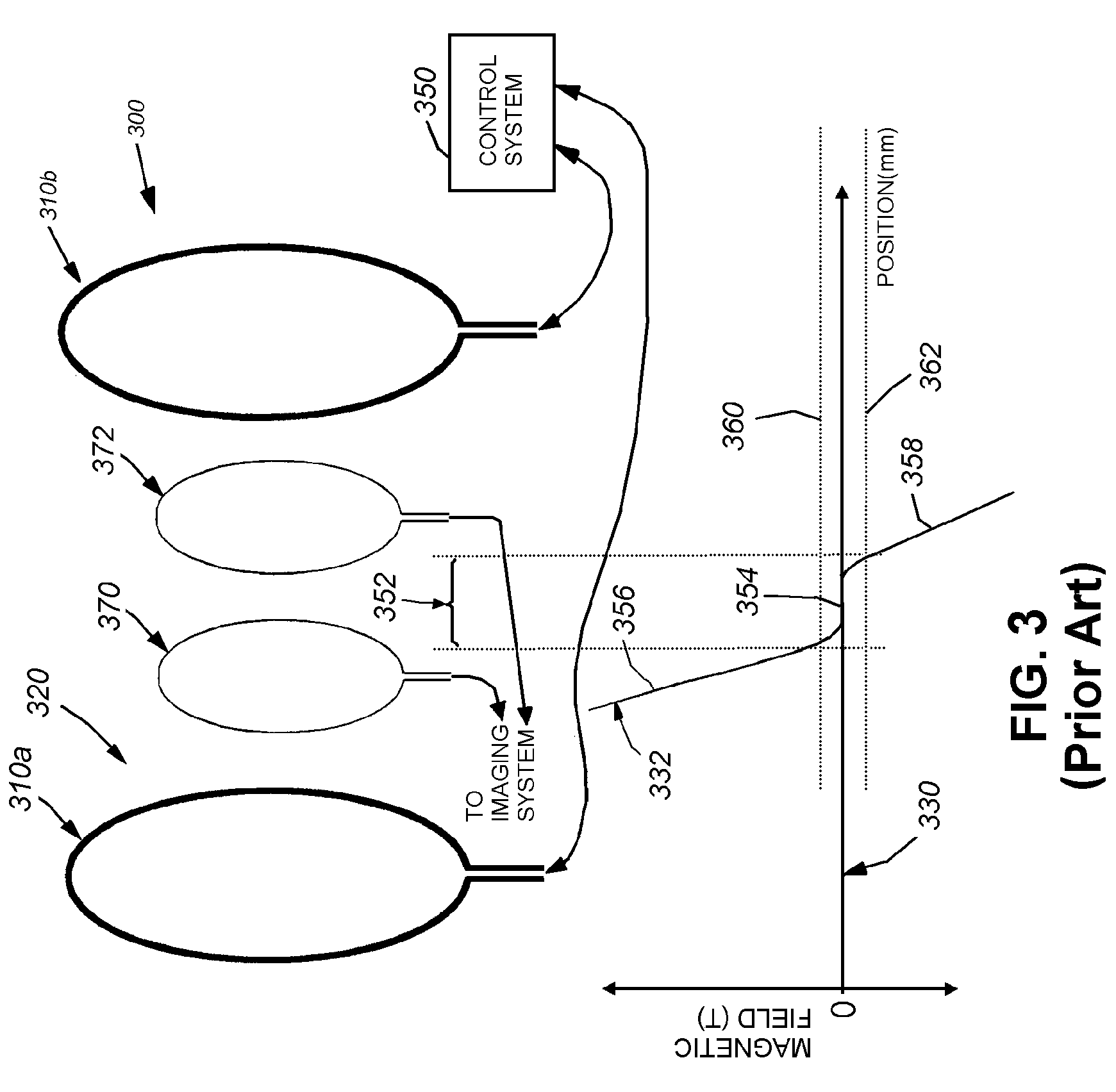
[0043]Reference is made to FIG. 3 which again describes a simplified MPI system 300 like the MPI system described above with reference to FIG. 1. This system 300 is again discussed and illustrated for the purposes of comparison with the following improved system arrangements described below. The views and graphs depicted are generally two-dimensional, but should be taken to describe the resulting field characteristics in three dimensions. The system 300 consists of groups of drive and selection coils 310a and 310b that define therebetween a magnetic field region 320 that can be characterized by the graph 330. The curve 332 defines the magnetic field across the subject produced by the coils to localize the nanoparticle signal versus position within to the region 320 (e.g. distance from either coil 310a, 310b). As described above, the selection and drive coils are operatively connected with a control system 350. The control system includes app...


PUM


Abstract

This invention provides a system and method that improves the sensitivity and localization capabilities of Magnetic Particle Imaging (MPI) by using combinations of time-varying and static magnetic fields. Combinations of magnetic fields can be used to distribute the signals coming from the magnetic particles among the harmonics and other frequencies in specific ways to improve sensitivity and to provide localization information to speed up or improve the signal-to-noise ratio (SNR) of imaging and / or eliminate the need for saturation fields currently used in MPI. In various embodiments, coils can be provided to extend the sub-saturation region in which nanoparticles reside; to provide a static field offset to bring nanoparticles nearer to saturation; to introduce even and odd harmonics that can be observed; and / or to introduce combinations of frequencies for more-defined observation of signals from nanoparticles. Further embodiments provide for reading of the signal produced by cyclically saturated magnetic nanoparticles in a sample so as to provide a measurement of the temperature of those nanoparticles. The spectral distribution of the signal generated provides estimates of the temperature of the nanoparticles. Related factors may also be estimated—binding energies of the nanoparticles, phase changes, bound fraction of the particles or stiffness of the materials in which the nanoparticles are imbedded.

Description

RELATED APPLICATIONS[0001]This application claims the benefit of U.S. Provisional Application Ser. No. 60 / 944,901, filed Jun. 19, 2007, entitled SYSTEM AND METHOD FOR IMPROVED NANOPARTICLE LOCALIZATION AND IMAGING, the entire disclosure of which is herein incorporated by reference and U.S. Provisional Application Ser. No. 60 / 974,105, filed Sep. 21, 2007, entitled SYSTEM AND METHOD FOR MEASURING TEMPERATURE USING THE SPECTRAL DISTRIBUTION OF MAGNETIC PARTICLE IMAGING SIGNALS, the entire disclosure of which is herein incorporated by reference.FIELD OF THE INVENTION[0002]This invention relates to non-invasive imaging of magnetic particles, and more particularly to Magnetic Particle Imaging (MPI), and to using magnetic particles as biomarkers for measuring particle temperature and binding characteristics of infused magnetic particles.BACKGROUND OF THE INVENTION[0003]The localization and imaging of magnetic particles and particularly nanoparticles (e.g. discrete particulate structures si...

Claims


Application Information

Patent Timeline
Patent Type & Authority Patents(United States)
IPC IPC(8): G01V3/00
CPCA61B5/05A61B5/0515B82Y25/00H01F1/0045
Inventor WEAVER, JOHN B.BAKER, IANHANSEN, ERIC W.
Owner DARTMOUTH HITCHCOCK CLINIC
Learn More