
Cooking device

a technology of cooking device and oven, which is applied in the direction of ventilation system, heating type, stove or range, etc., can solve the problems of motor overheating, and achieve the effects of enhancing the durability of the motor, enhancing the barrier properties, and increasing the volume of the cavity

Inactive Publication Date: 2011-08-09
SHARP KK
View PDF16 Cites 28 Cited by
  • Summary
  • Abstract
  • Description
  • Claims
  • Application Information

AI Technical Summary

Benefits of technology

The present invention relates to a cooking device for business use that has a fan and an exhaust duct for guiding air in a heating chamber. The invention aims to prevent hot air and steam from blowing off from the exhaust duct and entering the motor, which can cause damage and lower performance. The invention proposes a solution by using a cavity at the periphery of the output shaft of the motor and a covering plate to depress the conduction of hot air and outflow of steam. The invention also addresses the issue of cost by providing a low-cost standard specification product mass-produced by a motor manufacturer.

Problems solved by technology

However, in a cooking device for business use wherein a bladed wheel is located in an exhaust duct through which hot air and steam in a heating chamber is discharged and a motor for driving said bladed wheel is disposed outside the exhaust duct, thermal energy of hot air distributed in the exhaust duct is easily conducted from said bladed wheel to the motor and said motor tends to be overheated since the bladed wheel is made of metal in order to respond to a request for heat resistance.
Moreover, since an output shaft of the motor penetrates a wall plane of an exhaust duct with a void and exhaust blast increases the pressure of the inside of the exhaust duct to an ordinary pressure or a positive pressure, steam distributed in the exhaust duct easily flows along the output shaft of the motor and out to the motor side and condenses at the output shaft of the motor to be water droplets, and said water droplets enter a bearing with rotation of the output shaft to be mixed into lubricating oil and tend to lower lubricity.

Method used


Image

  • Cooking device
  • Cooking device
  • Cooking device

Examples


Embodiment Construction

[0047]The following description will explain the present invention in detail with reference to the drawings illustrating an embodiment thereof.

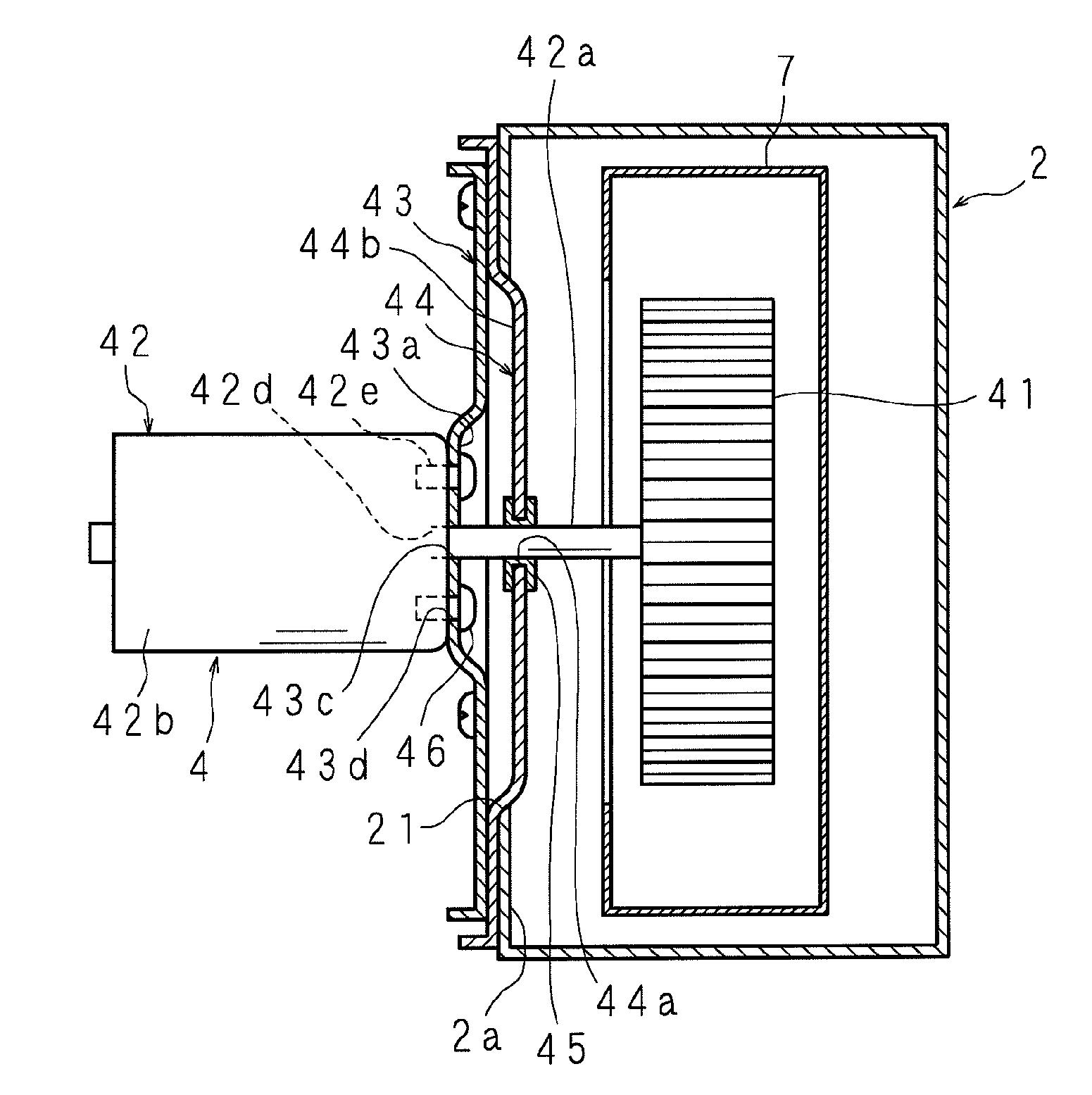
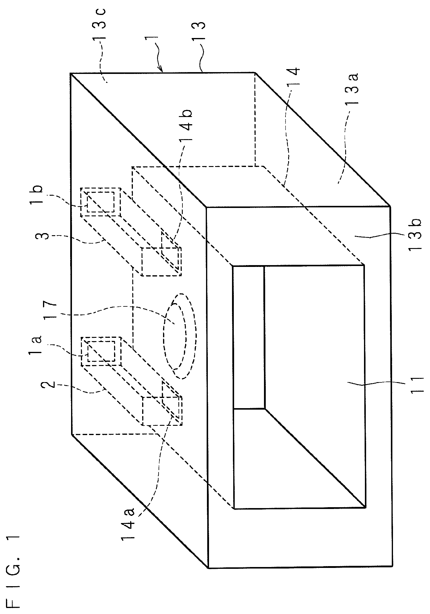
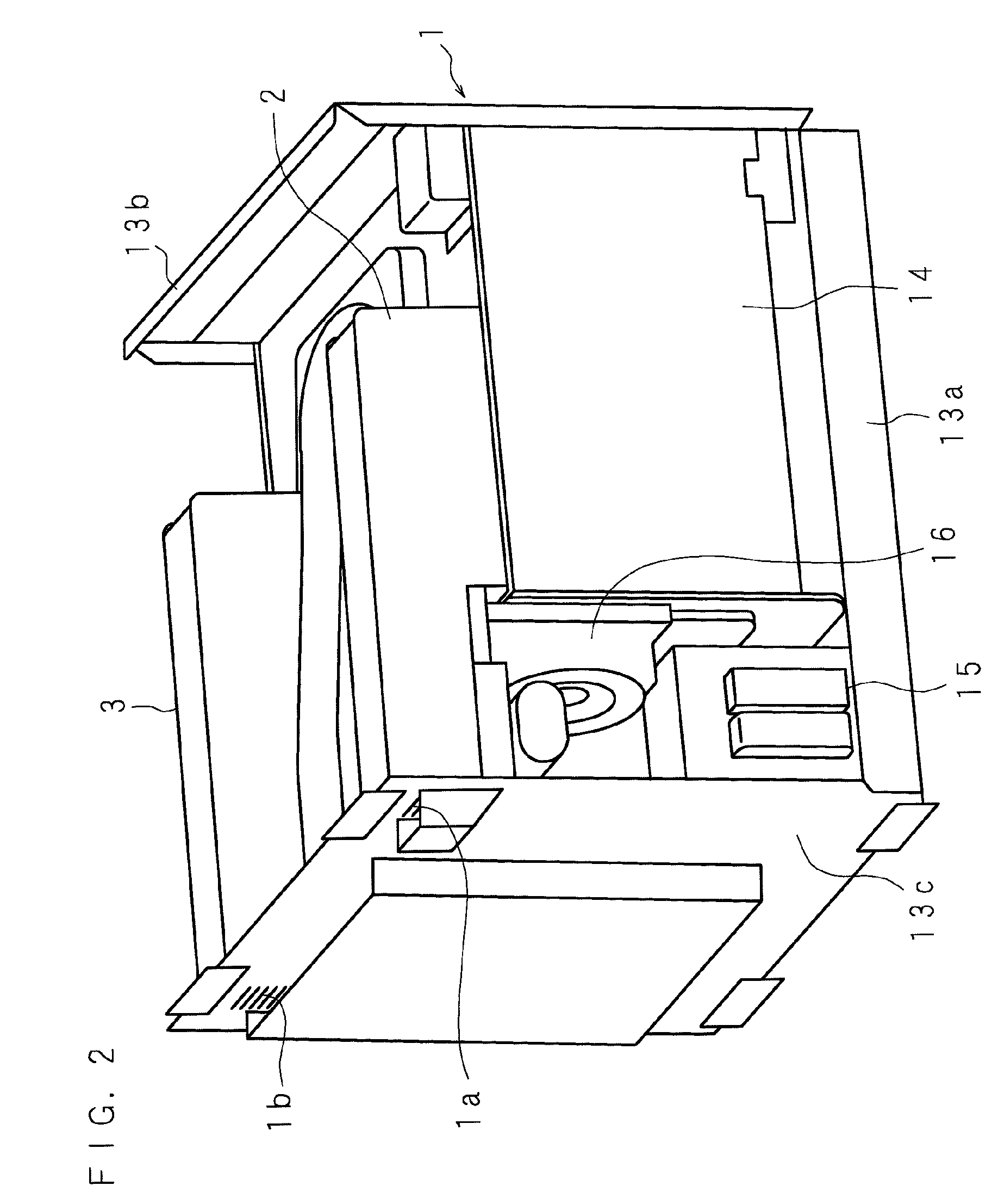
[0048]FIG. 1 is a schematic perspective view for showing the structure of a cooking device according to the present invention; FIGS. 2 and 3 are partial rear-side perspective views for showing the structure of a cooking device; FIG. 4 is a front view for showing the structure of a cooking device; FIG. 5 is a partial plan view for showing the structure of a cooking device; FIG. 6 is a partial rear view for showing the structure of a cooking device; FIG. 7 is a partial left side view for showing the structure of a cooking device; FIG. 8 is a partial right side view for showing the structure of a cooking device; FIG. 9 is a schematic sectional view for showing the structure of a cooking device; FIG. 10 is an exploded perspective view for showing the relation between an exhaust duct and a fan; and FIG. 11 is an enlarged sectional view of the part...


PUM


Abstract

A cooking device body having a heating chamber for heating an object; a fan for discharging air in the heating chamber; and an exhaust duct for guiding air blown off from said fan to the outside of the cooking device body are provided, an opening is provided at a wall of said exhaust duct, and the fan is constructed to have a motor disposed outside the exhaust duct, a first plate which has a central side attached to the motor and an outer edge side attached to the periphery of the opening, a bladed wheel which is attached to the output shaft of the motor and disposed in the exhaust duct, and a second plate which defines a cavity between said bladed wheel and the first plate.

Description

CROSS-REFERENCE TO RELATED APPLICATIONS[0001]This Nonprovisional application claims priority under 35 U.S.C. §119(a) on Patent Application No. 2008-11990 filed in Japan on Jan. 22, 2008, the entire contents of which are hereby incorporated by reference.BACKGROUND[0002]1. Technical Field[0003]The present invention relates to a cooking device such as a microwave oven for heating an object.[0004]2. Description of Related Art[0005]Cooking devices are divided into one for home use, which is located at a domestic kitchen to be used by family members, and one for business use, which is located at a kitchen in a hotel, a restaurant, a fast-food eatery or the like to be used by an employee or the like for serving a meal to a customer or the like. While one cooking device is located for home use since the cooking device is used only several times a day, generally a plurality of cooking devices are located for business use so as to immediately deal with demand for heat cooking since the cookin...

Claims


Application Information

Patent Timeline
Patent Type & Authority Patents(United States)
IPC IPC(8): F24C15/32
CPCF24C15/322H05B6/642
Inventor HIRANO, SEIICHINAKAMURA, TATSUHIKO
Owner SHARP KK
Learn More