
Radiographic image detection apparatus and method for controlling the apparatus

a radiographic image and detection apparatus technology, applied in the direction of radiation beam directing means, instruments, applications, etc., can solve the problems of deteriorating high etc., to prevent the deterioration of the image quality of the radiographic image and reduce the radiation dose of the subject.

Inactive Publication Date: 2011-07-26
FUJIFILM CORP
View PDF4 Cites 3 Cited by
  • Summary
  • Abstract
  • Description
  • Claims
  • Application Information

AI Technical Summary

Benefits of technology

The present invention provides a radiographic image detection apparatus that can prevent deterioration of image quality caused by a defect region in the detector and reduce the dose of radiation that the subject is exposed to. The apparatus includes a relative-position changing means that moves at least one of the detector and the subject to change their relative positions. A defect-region storage means stores the position of the defect region and the size and degree of defect of the defect region. An overlap judgment means judges whether the defect region overlaps with the region of interest. A movement amount calculation means calculates the relative movement amount for changing the relative positions of the detector and the subject. A movement control means controls the operation of the relative-position changing means based on the calculated movement amount. The invention also provides a method for controlling the radiographic image detection apparatus.

Problems solved by technology

In such cases, a defect region in which correct image information is not obtained is present in the radiographic image detector, and the presence of the defect region deteriorates the image quality of the radiographic image.
Therefore, there is a problem that the dose of radiation that irradiates the subject becomes high.

Method used


Image

  • Radiographic image detection apparatus and method for controlling the apparatus
  • Radiographic image detection apparatus and method for controlling the apparatus
  • Radiographic image detection apparatus and method for controlling the apparatus

Examples


Embodiment Construction

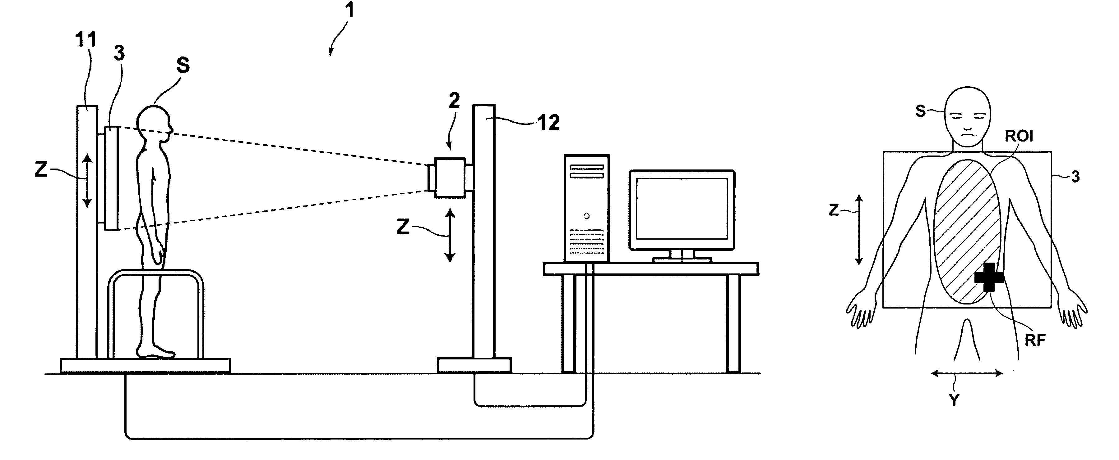
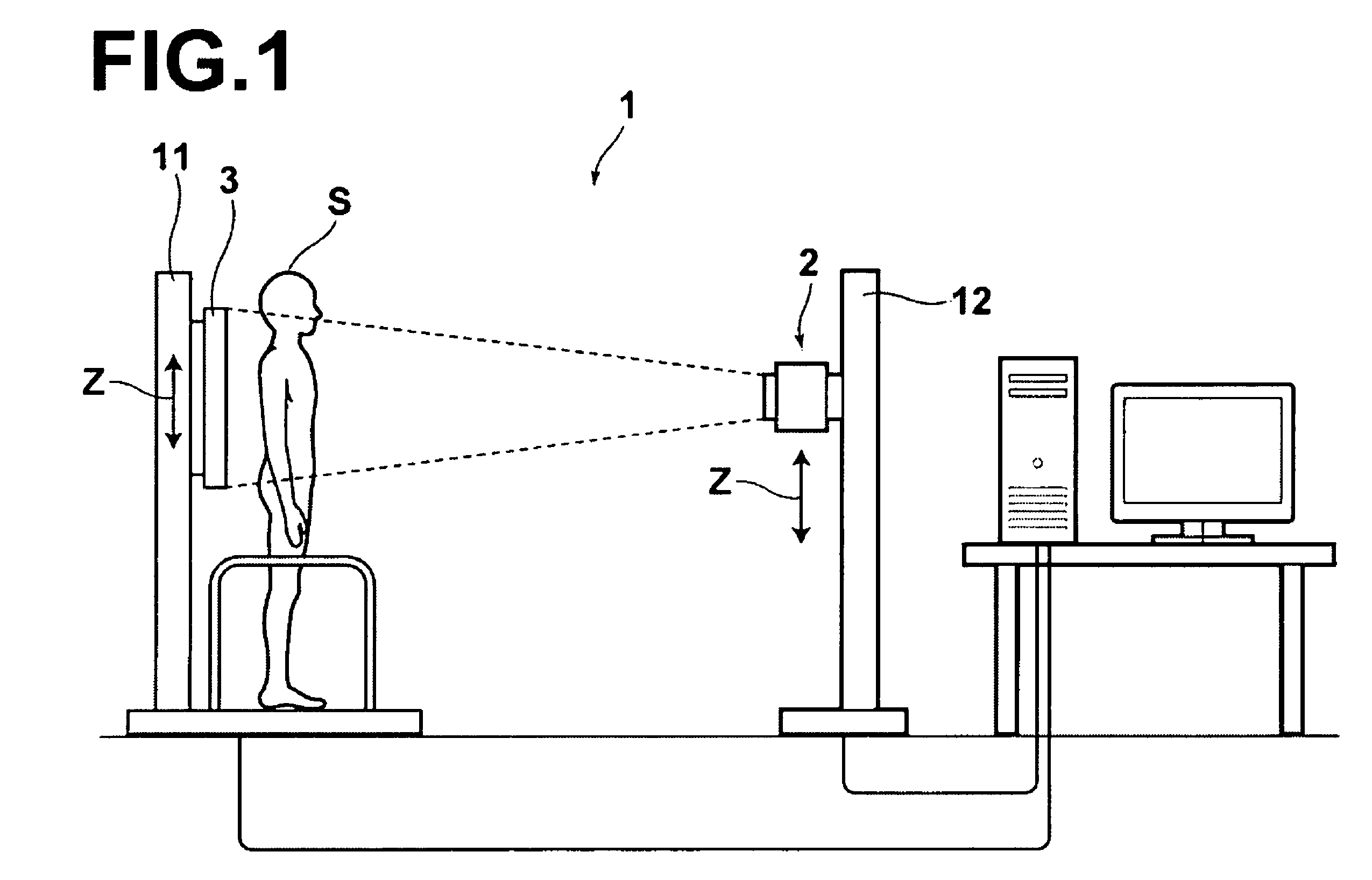
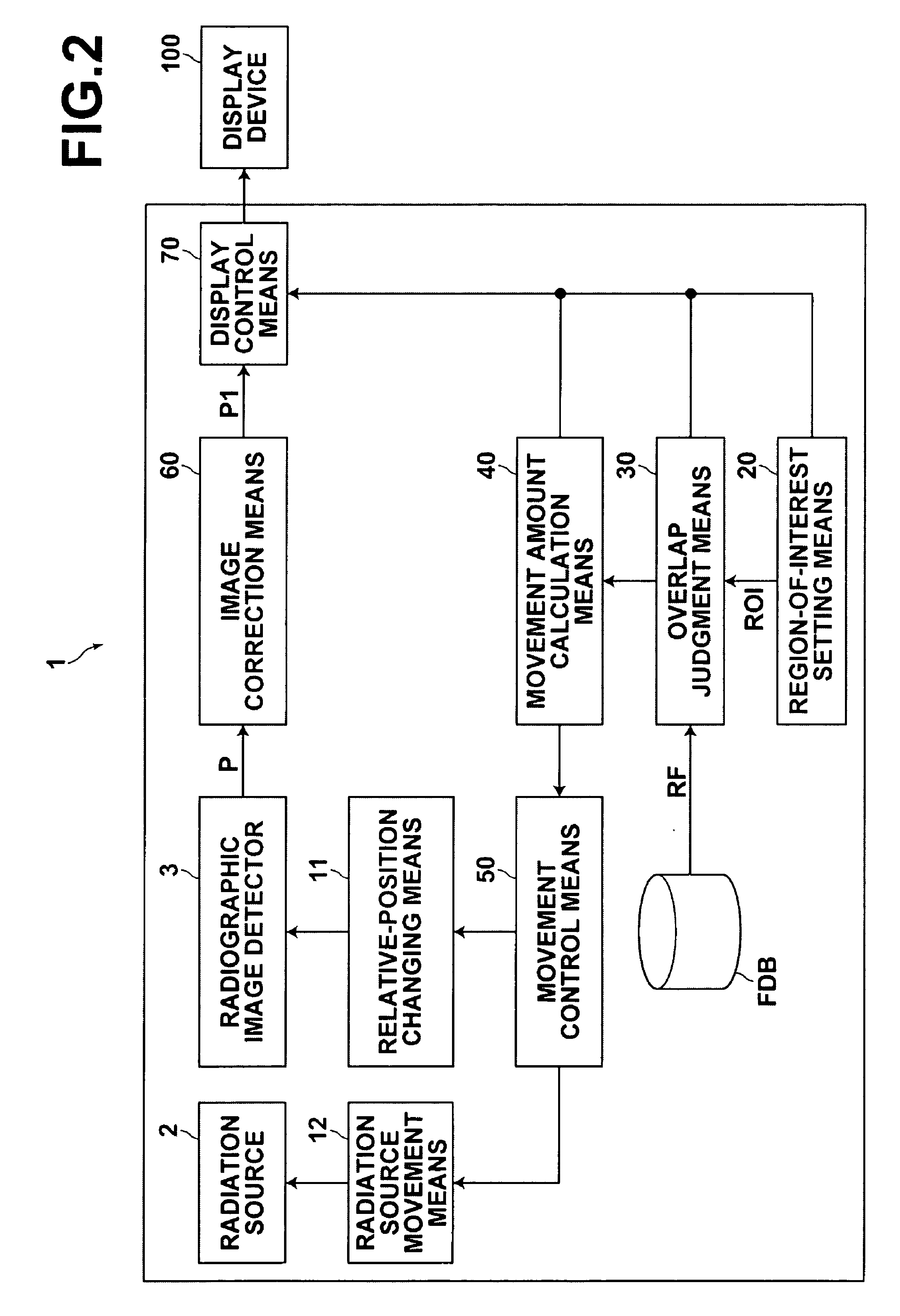
[0056]Hereinafter, a radiographic image detection apparatus of the present invention will be described with reference to drawings. FIG. 1 is a schematic diagram illustrating an embodiment of a radiographic image detection apparatus for obtaining radiographic images. FIG. 2 is a block diagram of the radiographic image detection apparatus. A radiographic image detection apparatus 1 includes a radiation source 2, a radiographic image detector 3, a relative-position changing means 11, and a radiation source movement means 12. The radiation source 2 outputs radiation to subject S. The radiation source 2 is controlled by a movement control means 50. The radiographic image detector 3 stores, as a static latent image, radiographic image information represented by radiation that has passed through the subject S. Further, when the static latent image stored in the radiographic image detector 3 is read out, the distribution of transmittance of radiation (which has passed through the subject S)...


PUM


Abstract

A region of interest is set in a state in which a subject is positioned in front of a radiographic image detector. Further, judgment is made as to whether a defect region is present in the region of interest. If the defect region is present in the region of interest, a relative movement amount of at least one of the subject and the radiographic image detector is calculated. After the at least one of the subject and the radiographic image detector is moved by the calculated relative movement amount, radiography is performed to detect a radiographic image.

Description

CROSS-REFERENCE TO RELATED APPLICATIONS[0001]The present application claims priority from Japanese Patent Application No. 2008-265866, filed Oct. 15, 2008, the contents of which are herein incorporated by reference in their entirety.BACKGROUND OF THE INVENTION[0002]1. Field of the Invention[0003]The present invention relates to a radiographic image detection apparatus that detects a radiographic image by irradiating a subject with radiation. Further, the present invention relates to a method for controlling the radiographic image detection apparatus.[0004]2. Description of the Related Art[0005]Conventionally, various kinds of radiation detectors (radiographic image detectors) have been proposed and practically used in medical fields, and the like. The radiation detectors store radiographic images related to subjects by irradiation with radiation that has passed through the subjects. One of the examples of such radiation detectors is a radiation detector using amorphous selenium, whi...

Claims


Application Information

Patent Timeline
Patent Type & Authority Patents(United States)
IPC IPC(8): H05G1/10
CPCA61B6/00A61B6/08A61B6/4476A61B6/469A61B6/542A61B6/545
Inventor KOTANI, MANABU
Owner FUJIFILM CORP
Learn More