
Wireless mobile communication system without pilot signals

a mobile communication system and pilot signal technology, applied in the field of wireless communication systems, can solve the problems of interference in wireless signal processing, reduced usable communication channels on allocated frequencies, and difficult signal processing, and achieve the effect of reducing the effect of transient interference in the receiver

Inactive Publication Date: 2011-07-26
BANK MICHAEL +3
View PDF6 Cites 2 Cited by
  • Summary
  • Abstract
  • Description
  • Claims
  • Application Information

AI Technical Summary

Benefits of technology

[0024]A guard interval may be added to each symbol before transmission of said symbol, for reducing the effect of transient interference in the receiver. A guard interval may be identified and removed from each symbol. The transmitter and receiver can each be stationary or mobile.

Problems solved by technology

However, some of the bearable signal interferences that exist at low frequencies communications increase drastically in higher frequencies, making signal processing more difficult.
In some cases the difficulty of signal processing reduces the number of usable communication channels on the allocated frequencies.
One of the interferences in wireless signal processing is caused by the Doppler-shift, which occurs when the transmitter and / or receiver is in motion, like in a moving car.
Other difficulties arise from known multi-path propagation delays of wireless signals and normal reflections of the signals themselves, which distort the original signal even further, especially in high frequencies where their impact is more significant.
However, a constant delay does not pose a serious problem for the signal processing as long as the delay is consistent; the problem lies with the unpredictable varying delays.
However, transmitting additional test signals burdens the allocated frequencies even further, wasting some of the precious communicating channels.
Furthermore, these test signals can only estimate the delays of the other signals without conviction, as some of the delays are data driven and some of the signals are not close enough to a test signal in the time and frequency domain.
However, this publication fails to disclose a method for systems using phase and amplitude coding.
Furthermore, it does not disclose a solution for canceling the Doppler-shift, multi-path propagation delay, or reflection interferences without using a test signal.

Method used


Image

  • Wireless mobile communication system without pilot signals
  • Wireless mobile communication system without pilot signals
  • Wireless mobile communication system without pilot signals

Examples


Embodiment Construction

[0050]For the sake of brevity some of the terms which are used hereinafter are described explicitly:

TDM and FDM

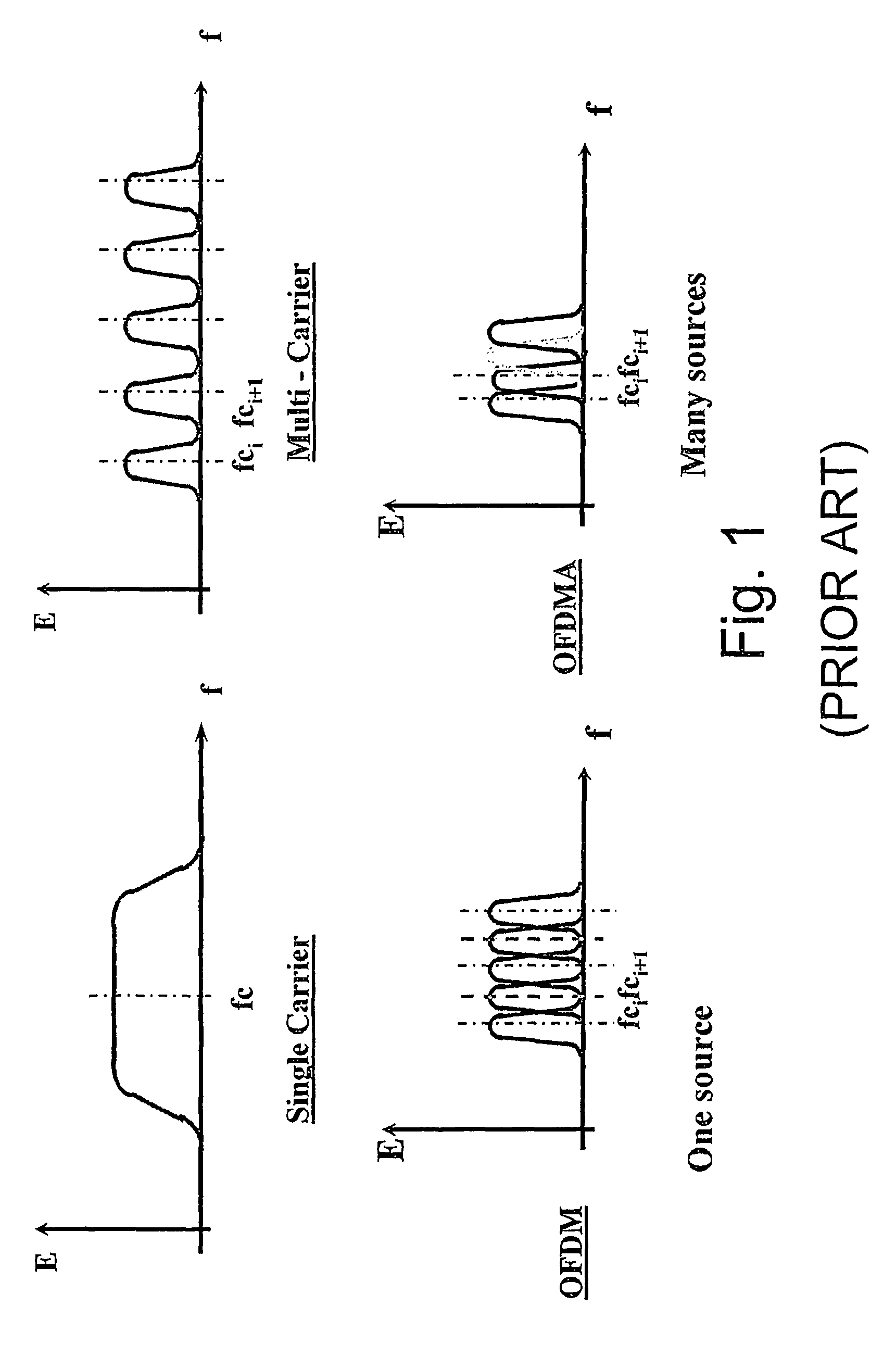
[0051]In order to have a better use of communication channels, several communication systems use multiplexing, whether in the time domain TDM (Time-Division Multiplexed) or in the frequency domain FDM (Frequency-Division Multiplexed). The signals received from different sources are multiplexed together and demultiplexed for transmitting many signals on the same communication channel. Even though in FDM several carriers are transmitted simultaneously, each carrier is modulated independently regardless of other carriers, thus conveying a different source of information. The final transmitted signal is a summation of all the modulated carriers. Nevertheless, two different sources can not utilize the same set of RF carriers due to mutual interference.

Orthogonal Frequency Division Multiplexing (OFDM)

[0052]According to the OFDM technique, a communication channel comprises m ortho...


PUM


Abstract

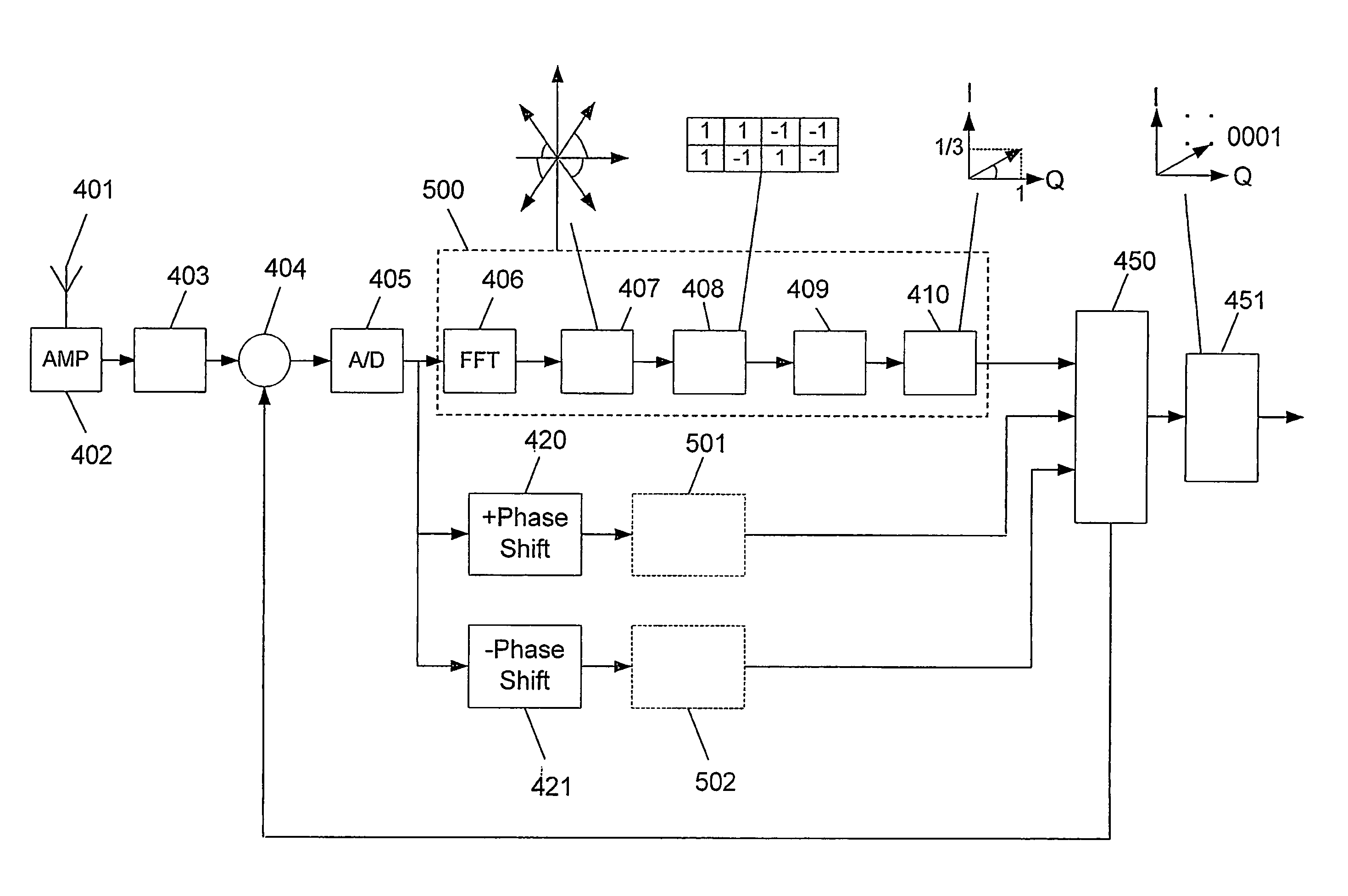
Method and system for allowing abandoning pilot signals use and for increasing the immunity to Doppler Effect influence in OFDMA based wireless mobile communication systems and as a result, make them more efficient. This is carried out by transmitting N orthogonal I and Q values of symbols, N times on N frequencies, where N is a power of two. In order to be able to select the desired signal from a mixture of N signals, signs of symbol of each signal vary according to one of N-order Walsh functions.

Description

FIELD OF THE INVENTION[0001]The present invention relates to the field of wireless communication systems. More particularly, the invention relates to a method for canceling the Doppler shift, multi-path propagation delays, and reflection influences of received Radio Frequency (RF) carriers, without using a pilot or test signal.BACKGROUND OF THE INVENTION[0002]With the growing amount of wireless communications, the need for more communication channels has driven providers to use more frequencies of higher spectrums. However, some of the bearable signal interferences that exist at low frequencies communications increase drastically in higher frequencies, making signal processing more difficult. In some cases the difficulty of signal processing reduces the number of usable communication channels on the allocated frequencies.[0003]One of the interferences in wireless signal processing is caused by the Doppler-shift, which occurs when the transmitter and / or receiver is in motion, like in...

Claims


Application Information

Patent Timeline
Patent Type & Authority Patents(United States)
IPC IPC(8): H04L5/12
CPCH04L5/0016H04L25/0238H04L27/0008H04L27/02H04L27/10H04L27/18H04L27/2605H04L27/2613H04L27/2655
Inventor BANK, MICHAELHILL, BORISBANK, MIRIAMHILL SELECTER, HANIT
Owner BANK MICHAEL
Learn More