Microscope apparatus and cell observation method
a microscope and cell technology, applied in the field of microscope apparatuses, to achieve the effect of rapid and efficient observation of cell states
- Summary
- Abstract
- Description
- Claims
- Application Information
AI Technical Summary
Benefits of technology
Problems solved by technology
Method used
Image

Examples
first embodiment
[0038]A microscope apparatus A according to a first embodiment of the present invention will be described below with reference to the drawings.
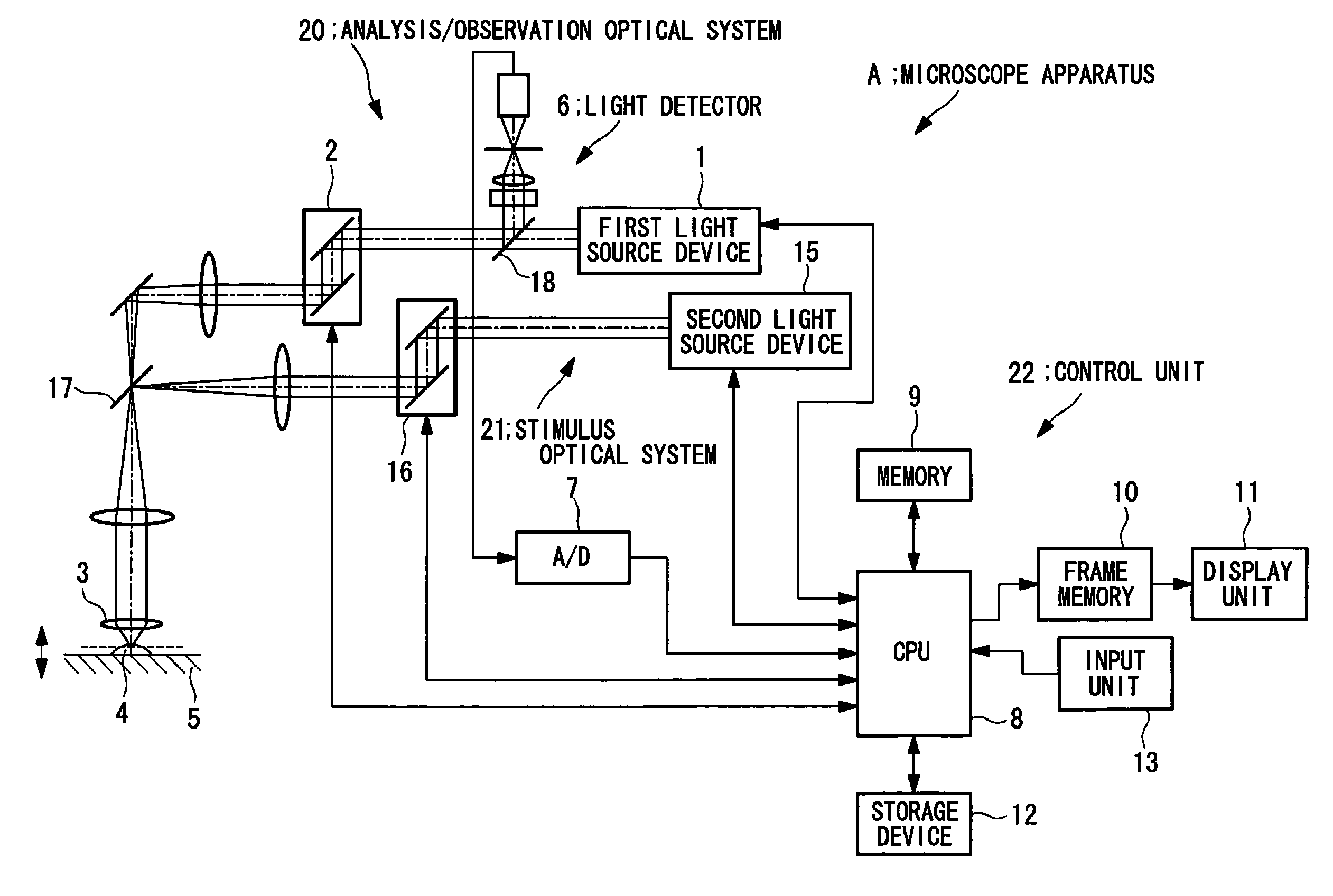
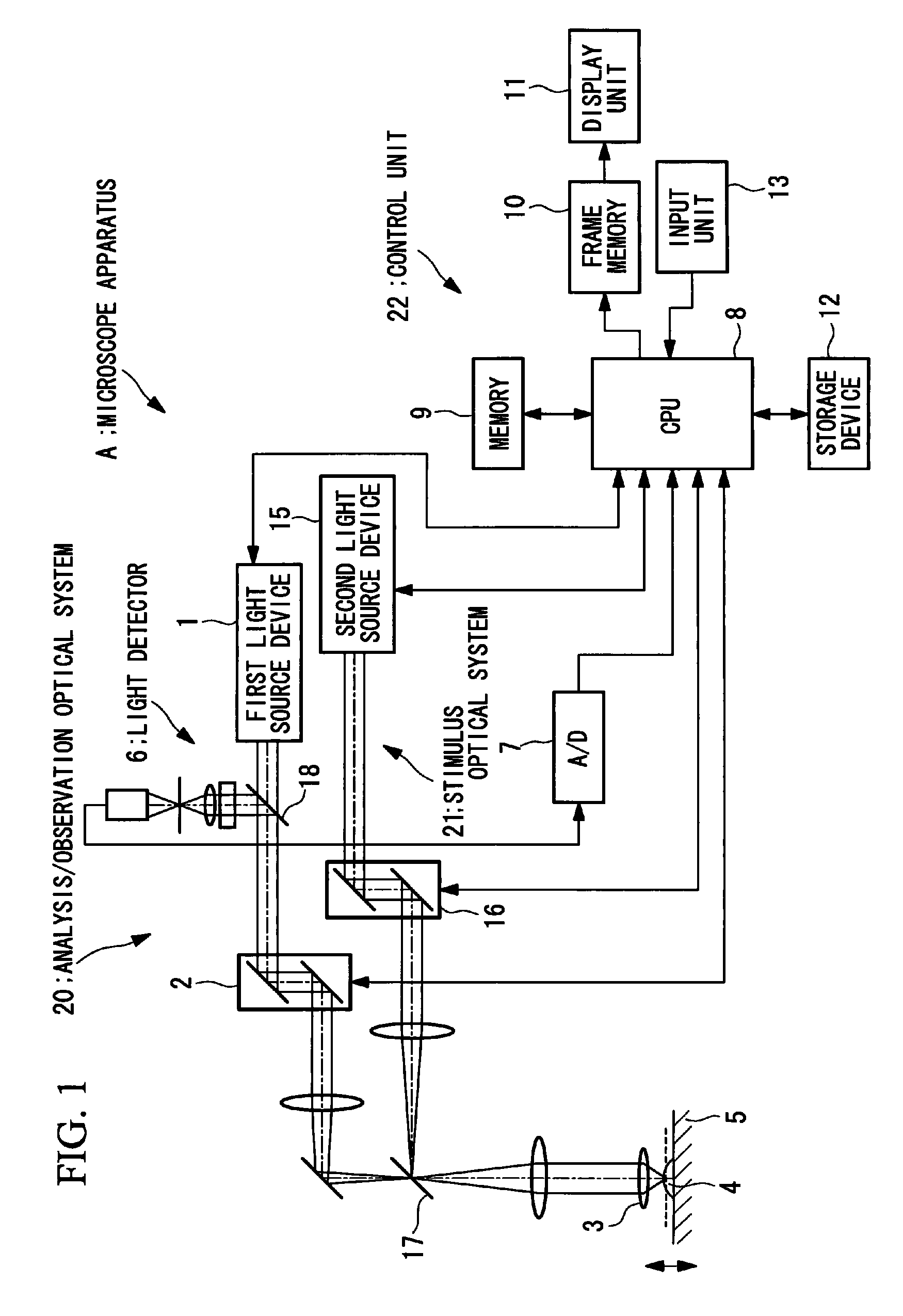
[0039]The microscope apparatus A according to this embodiment is a laser scanning microscope. In FIG. 1, optical components such as various lenses and pinholes have been appropriately omitted to simplify the description.
[0040]As shown in FIG. 1, the microscope apparatus A according to this embodiment includes an analysis / observation optical system 20 and a stimulus optical system 21. The analysis / observation optical system 20 is used for identifying the cell phases of a plurality of cells mounted on a stage 5, as well as for acquiring an observed image of the cells. The stimulus optical system 21 is used for applying an optical stimulus to a prescribed cell.
[0041]The analysis / observation optical system 20 includes a first light source device 1 for selectively emitting analysis laser light for identifying the cell phase or observation laser li...
second embodiment
[0082]Next, a second embodiment of the present invention will be described using the drawings.
[0083]As shown in FIG. 8, the microscope apparatus of this embodiment differs from that in the first embodiment in that the fluorescence of the cells is detected with a CCD (image-acquisition unit) 25. In this figure, an illustration of the analysis / observation optical system 20 is omitted. This analysis / observation optical system 20 may be configured as a standard microscope optical system, or it may be a disk scanning optical system using a confocal disk provided with numerous minute apertures.
[0084]With this configuration, because the fluorescence excited in the cells is imaged by the CCD 25, it is possible to acquire fluorescence images at high speed.
[0085]In this embodiment, the amount of cell components of each cell, in other words, the total fluorescence brightness and the maximum fluorescence brightness of each cell, is determined using the fluorescence images acquired by the CCD 25...
third embodiment
[0086]Next, a third embodiment of the present invention will be described using the drawings.
[0087]As shown in FIG. 9, the microscope apparatus of this embodiment differs from that in the first embodiment in that it is constructed using a shared optical system for the analysis / observation optical system and the stimulus optical system.
[0088]More specifically, an analysis / observation / stimulus optical system 30 according to this embodiment includes a third light source device 26 for selectively emitting one type of laser light, either analysis laser light for identifying the cell phase, observation laser light for observing the cells, or optical stimulus laser light; and a first scanner 2 which two-dimensionally moves the laser light emitted from the third light source device 26 in directions intersecting the optical axis.
[0089]Accordingly, in the cell-phase-identifying process, only the analysis laser light is emitted from the third light source device 26; in the optical stimulus pro...
PUM
| Property | Measurement | Unit |
|---|---|---|
| optical stimulus | aaaaa | aaaaa |
| fluorescence | aaaaa | aaaaa |
| brightness | aaaaa | aaaaa |
Abstract
Description
Claims
Application Information
 - R&D
- Intellectual Property
- Life Sciences
- Materials
- Tech Scout
- Unparalleled Data Quality
- Higher Quality Content
- 60% Fewer Hallucinations
Browse by: Latest US Patents, China's latest patents, Technical Efficacy Thesaurus, Application Domain, Technology Topic, Popular Technical Reports.
© 2025 PatSnap. All rights reserved.Legal|Privacy policy|Modern Slavery Act Transparency Statement|Sitemap|About US| Contact US: help@patsnap.com