
Magetic latching relay

a latching relay and magnetic technology, applied in the field of relays, can solve the problems of large round arch-shaped bends and unsteady flexibility, and achieve the effects of avoiding large occupied space and unsteady flexibility, high current, and low power consumption

Inactive Publication Date: 2011-07-19
SHANGHAI BST ELECTRICAL APPLIANCE MFG
View PDF4 Cites 10 Cited by
  • Summary
  • Abstract
  • Description
  • Claims
  • Application Information

AI Technical Summary

Benefits of technology

"The present invention is a magnetic latching relay that improves the structure of the movable contact spring assembly and relevant structures to avoid the influence of erection stress on internal structural parameters. The relay includes a yoke assembly, magnetic steel assembly, contact system, pusher pad, and shell. The back contact springs are arc-shaped and stacked on one side of each movable contact spring, and the bottom case has clip-shaped bosses to fasten the springs and support them with bolts to clamp them. The invention avoids large occupied space and unsteady flexibility caused by the projection of the back contact springs. The springs are well-clamped to avoid the influence of erection stress on the internal structural parameters of the relay. The invention is especially applicable for two-phase magnetic latching relays."

Problems solved by technology

Previously the round arch-shaped bends are large and have an unsteady flexibility.

Method used


Image

  • Magetic latching relay
  • Magetic latching relay
  • Magetic latching relay

Examples


Embodiment Construction

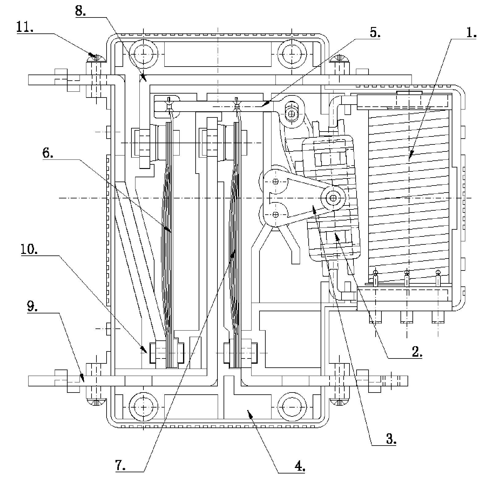
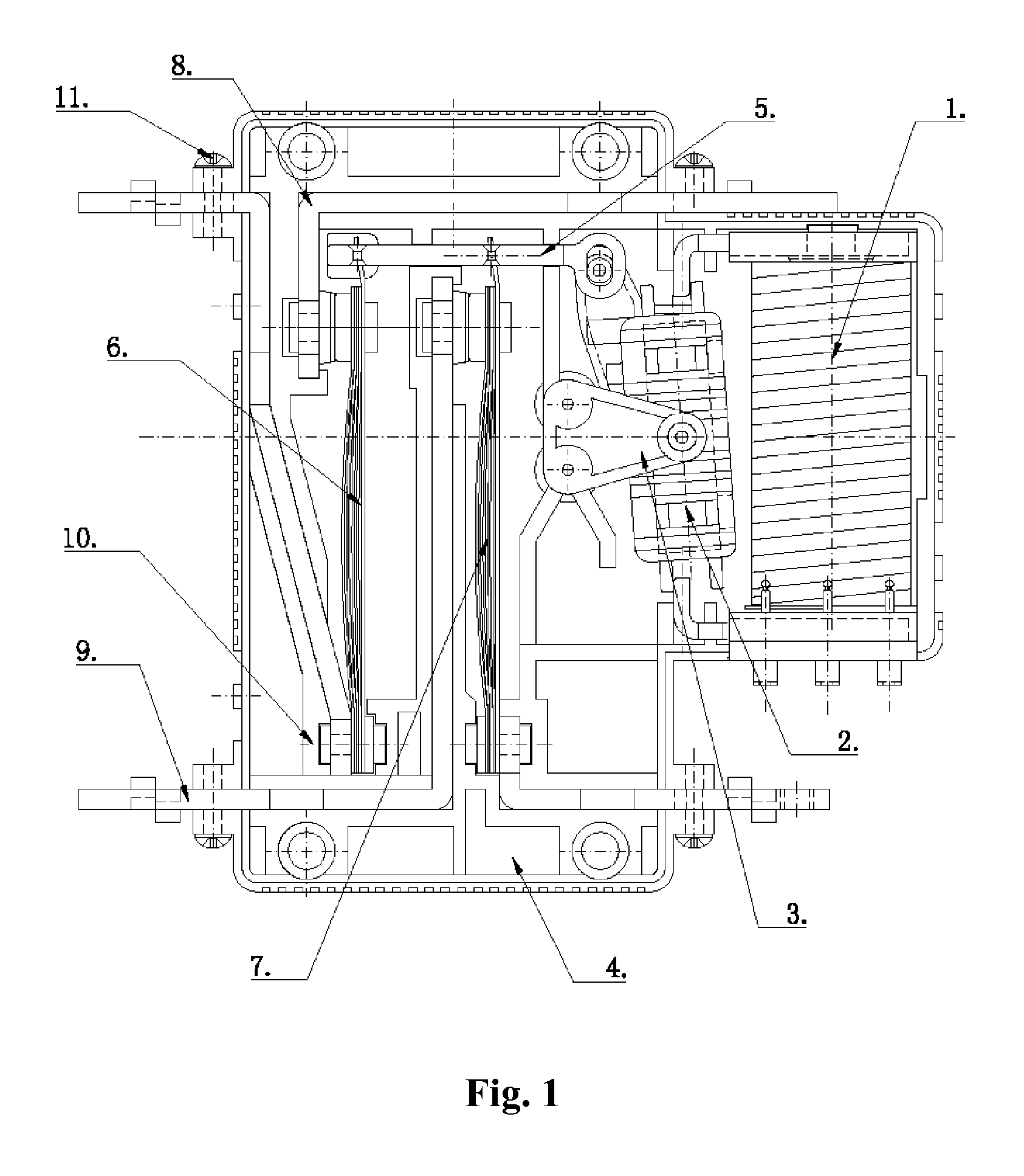
[0024]As shown in FIG. 1, a magnetic latching relay according to the present invention includes a yoke assembly 1, a magnetic steel assembly 2, a contact system and a shell 4. The yoke assembly 1 includes a single coil or double coils, and double yokes. For the double coils, if electrified by any phase of three-phase power, the relay will normally work, and overlapped opening and shutdown signals only lead to non-operation of the relay thereby avoiding disaster caused by short circuit between the phases. This is the greatest advantage of two drive coils, which is hardly achieved by a single drive coil.

[0025]The magnetic steel assembly 2 is an integrated one including a cylindrical shaft, a magnetic steel and a plastic armature. A supporting frame 3 for mounting the shaft of the magnetic steel assembly 2 is tongue-shaped or triangular. A pin in a rearside of supporting frame 3 is plug-connected with a tubular jack on a partitioned locating and dividing slot board of the magnetic stee...


PUM


Abstract

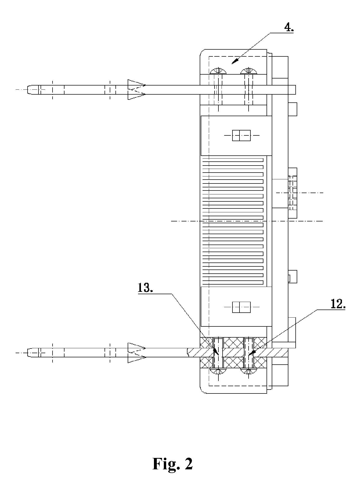
The present invention relates to a magnetic latching relay which can avoid influences of erection stress on internal structure parameters thereof. The magnetic latching relay includes a yoke assembly, a magnetic steel assembly, a contact system having movable and immovable contact spring assemblies and a pusher pad, and a shell having a bottom case and an upper cover. Back contact springs of the movable contact spring assembly are arc-shaped and stacked on one side of each movable contact spring of the movable contact spring assembly. The bottom case has clip-shaped bosses which are formed outside two side walls of the bottom case to fasten extension ends of the movable and the immovable contact springs and supported with bolts to clamp the springs extending out of clip-shaped openings of the bosses.

Description

CROSS-REFERENCE TO RELATED APPLICATIONS[0001]This application claims priority benefits to Chinese Patent Application No. 200720074176.7 filed Aug. 28, 2007and Chinese Patent Application No. 200720074746.2 and Sep. 17, 2007. The contents of all of the aforementioned specifications are incorporated herein by reference.BACKGROUND OF THE INVENTION[0002]1. Field of the Invention[0003]The present invention is related to basic electric elements, and more especially to a relay.[0004]2. Description of the Related Art[0005]A relay includes a yoke assembly, a magnetic steel assembly, a contact system and a shell. The yoke assembly is composed of coils and yokes. The magnetic steel assembly is an integrated one including a cylindrical shaft, a magnetic steel and a plastic armature, and the cylindrical shaft is installed in an axle hole defined by a bottom case of the shell and a tongue-shaped or triangular supporting frame that is plug-connected with a locating and dividing slot board of the ma...

Claims


Application Information

Patent Timeline
Patent Type & Authority Patents(United States)
IPC IPC(8): H01H51/22
CPCH01H1/28
Inventor YANG, ZHENGWANG, ZHONGQIN
Owner SHANGHAI BST ELECTRICAL APPLIANCE MFG
Learn More