
System and method for controlling overshoot and undershoot in a switching regulator

a switching regulator and system technology, applied in the field of semiconductor circuits, can solve the problems of reducing the efficiency of the switching regulator, and increasing the switching frequency, so as to reduce the magnitude of the transient overshoot or the transient undershoot, and improving the performance of the switching regulator

Active Publication Date: 2011-07-19
NAT SEMICON CORP
View PDF18 Cites 34 Cited by
  • Summary
  • Abstract
  • Description
  • Claims
  • Application Information

AI Technical Summary

Benefits of technology

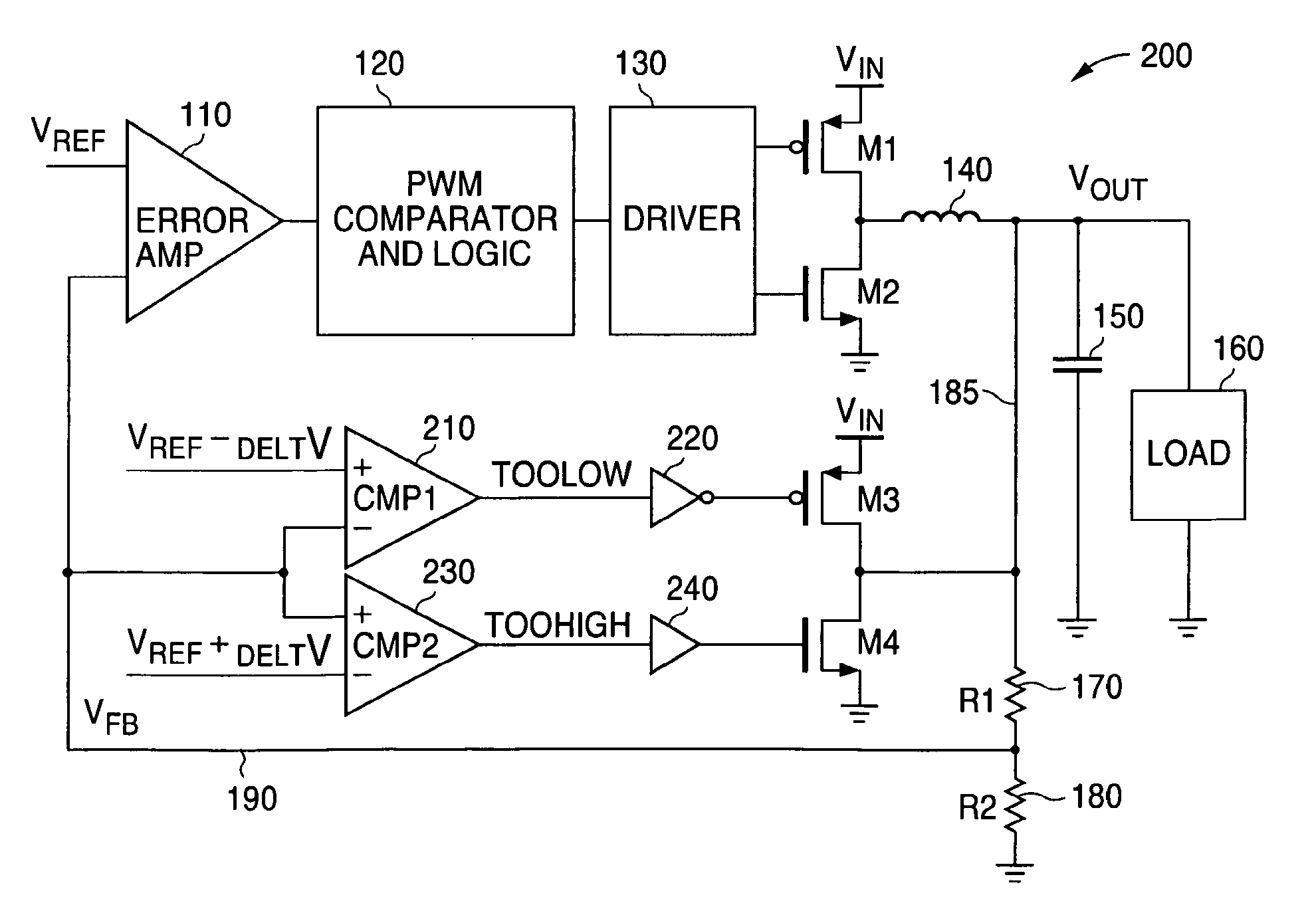
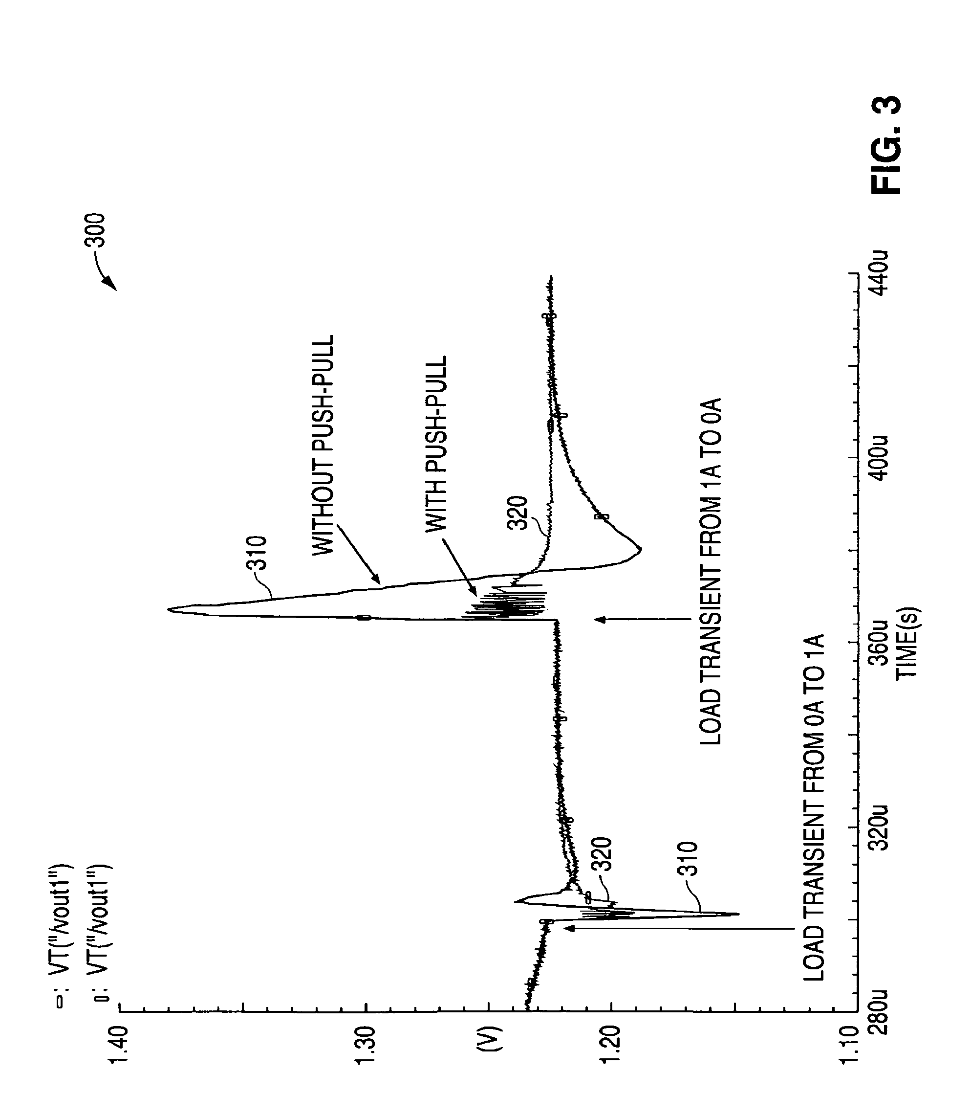
[0005]To address the above-discussed deficiencies of the prior art, it is a primary object of the present invention to provide a system and method for improving the performance of a switching regulator to reduce the magnitude of a transient overshoot or a transient undershoot when the size of a load is suddenly reduced or increased.

Problems solved by technology

When a load is suddenly reduced or suddenly increased in a switching regulator, the value of the output voltage usually exhibits an overshoot in value or an undershoot in value.
There are also certain disadvantages in using smaller sized inductors.
Increasing the switching frequency reduces the efficiency of the switching regulator.

Method used


Image

  • System and method for controlling overshoot and undershoot in a switching regulator
  • System and method for controlling overshoot and undershoot in a switching regulator
  • System and method for controlling overshoot and undershoot in a switching regulator

Examples


Embodiment Construction

[0017]FIGS. 1 through 7 and the various embodiments used to describe the principles of the present invention in this patent document are by way of illustration only and should not be construed in any way to limit the scope of the invention. Those skilled in the art will understand that the principles of the present invention may be implemented in any type of suitably arranged switching regulator.

[0018]To simplify the drawings the reference numerals from previous drawings will sometimes not be repeated for structures that have already been identified.

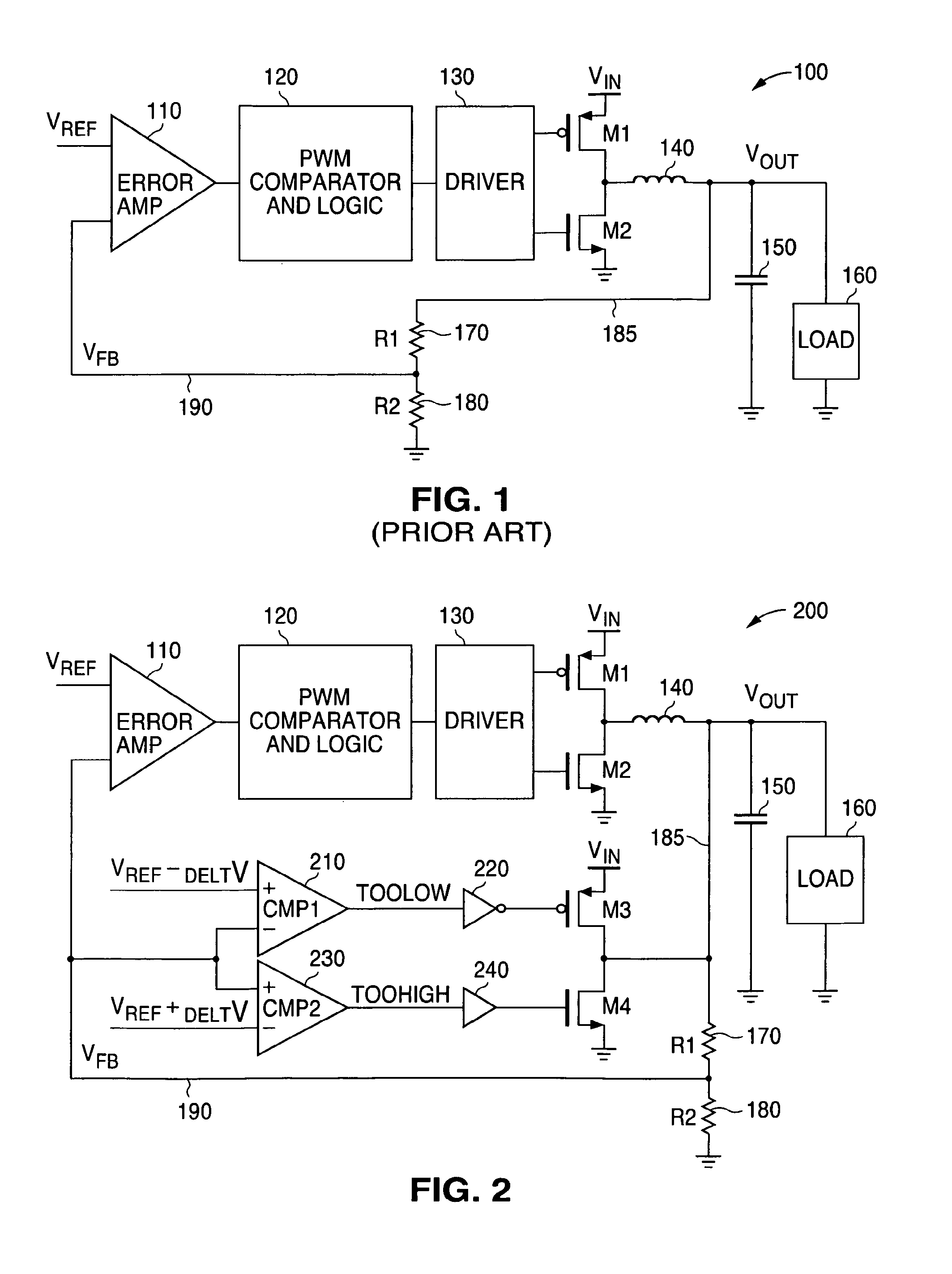
[0019]FIG. 1 illustrates a typical prior art switching regulator 100. The switching regulator 100 comprises an error amplifier 110, a pulse width modulation (PWM) comparator and logic unit 120, and a driver unit 130 connected as shown in FIG. 1. A first input to the error amplifier 110 receives a reference voltage VREF. A first output of the driver unit 130 is connected to the gate of a p-type metal oxide semiconductor (PMOS) transistor ...


PUM


Abstract

A system and a method are disclosed for controlling overshoot and undershoot in a switching regulator circuit. A first comparator circuit for controlling an undershoot of an output voltage of the switching regulator circuit is provided that that detects an occurrence of an undershoot of the output voltage of the switching regulator circuit and activates a first current source to pull up the output voltage of the switching regulator circuit. A second comparator circuit for controlling an overshoot of an output voltage of the switching regulator circuit is provided that detects an occurrence of an overshoot of the output voltage of the switching regulator circuit and activates a second current source to pull down the output voltage of the switching regulator circuit.

Description

TECHNICAL FIELD OF THE INVENTION[0001]The present invention is generally directed to the semiconductor circuits and, in particular, to a system and method for controlling overshoot and undershoot in a switching regulator.BACKGROUND OF THE INVENTION[0002]When a load is suddenly reduced or suddenly increased in a switching regulator, the value of the output voltage usually exhibits an overshoot in value or an undershoot in value. The magnitude of the overshoot or undershoot depends on the size of various elements of the regulator. For example, the magnitude of the overshoot or undershoot may depend on the size of the inductor, the size of the output capacitor, the equivalent series resistance (ESR) of the output capacitor, the switching regulator control loop bandwidth and the switching frequency.[0003]Using smaller sized inductors and larger sized capacitors generally minimizes the magnitude of the overshoot or undershoot. Design requirements, however, generally call for smaller size...

Claims


Application Information

Patent Timeline
Patent Type & Authority Patents(United States)
IPC IPC(8): G05F1/40
CPCH02M3/158H02M2001/0045H02M1/0045
Inventor XIN-LEBLANC, JANE
Owner NAT SEMICON CORP
Learn More