
System and method for real-time monitoring and failure prediction of electrical submersible pumps

a technology of electrical submersible pumps and real-time monitoring, which is applied in the direction of positive displacement liquid engines, instruments, nuclear elements, etc., can solve the problems of unwanted well intervention activities such as workovers, difficult to achieve, and expensive over the operational lifetime of the pump system, so as to achieve accurate prediction of pump failures and simple and user-friendly mechanisms

Inactive Publication Date: 2011-07-12
SCHLUMBERGER TECH CORP
View PDF15 Cites 48 Cited by
  • Summary
  • Abstract
  • Description
  • Claims
  • Application Information

AI Technical Summary

Benefits of technology

Enables a wide range of operators to predict pump failures accurately and efficiently, reducing monitoring costs by providing a simple and intuitive interface for fault prediction and update capabilities.

Problems solved by technology

During extended operation, the components of the electrical submersible pump may be subject to degradation or breakage, which can lead to unwanted well intervention activities such as workovers.
Disadvantageously, current monitoring systems require experienced operators to monitor and analyze in detail the operating conditions of the pump in order to identify operating conditions that predict if and when failure of the pump system is imminent.
Employing such an experienced operator (or providing an inexperienced operator with the necessary amount of training) is difficult to accomplish and costly over the operational lifetime of the pump system.

Method used


Image

  • System and method for real-time monitoring and failure prediction of electrical submersible pumps
  • System and method for real-time monitoring and failure prediction of electrical submersible pumps
  • System and method for real-time monitoring and failure prediction of electrical submersible pumps

Examples


Embodiment Construction

[0022]The present invention generally relates to a system and method for real-time monitoring and failure prediction of electrical submersible pumps. The system and method employ real-time data acquisition and monitoring of the downhole pumping system along with automatic computer-implemented fault prediction. Such fault prediction enables the well operator (or well field manager) to more efficiently and effectively predict failure of the downhole pumping system before it occurs, thereby minimizing the risk of catastrophic failure and the costs associated therewith.

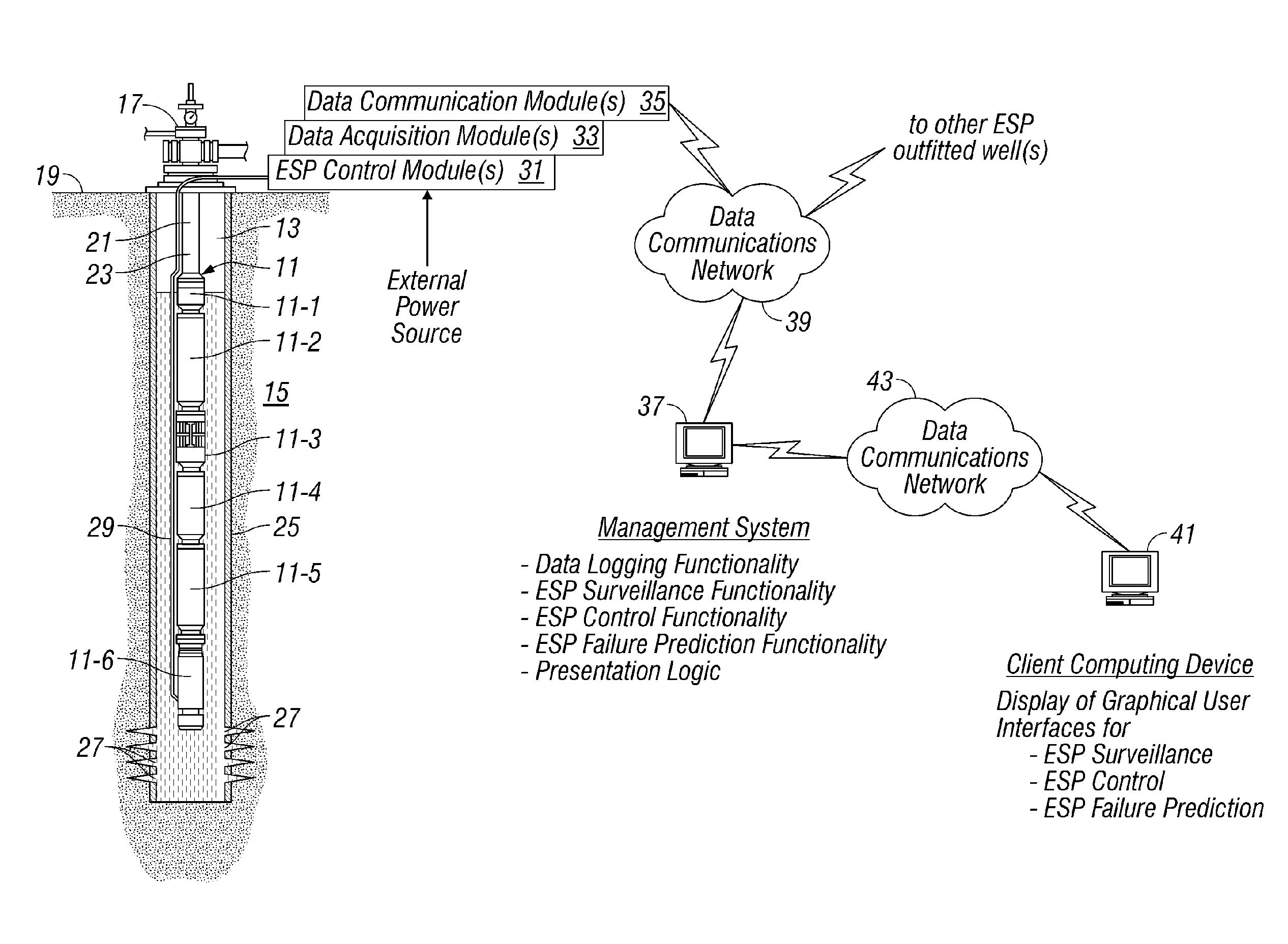
[0023]Turning now to FIG. 1, an exemplary electrical submersible pumping system 11 is shown disposed within a wellbore 13 drilled or otherwise formed in a geological formation 15. Electrical submersible pumping system 11 is suspended below a wellhead 17 disposed, for example, at a surface 19 of the earth. Pumping system 11 is suspended by a deployment system 21, such as production tubing, coiled tubing, or other deploymen...


PUM


Abstract

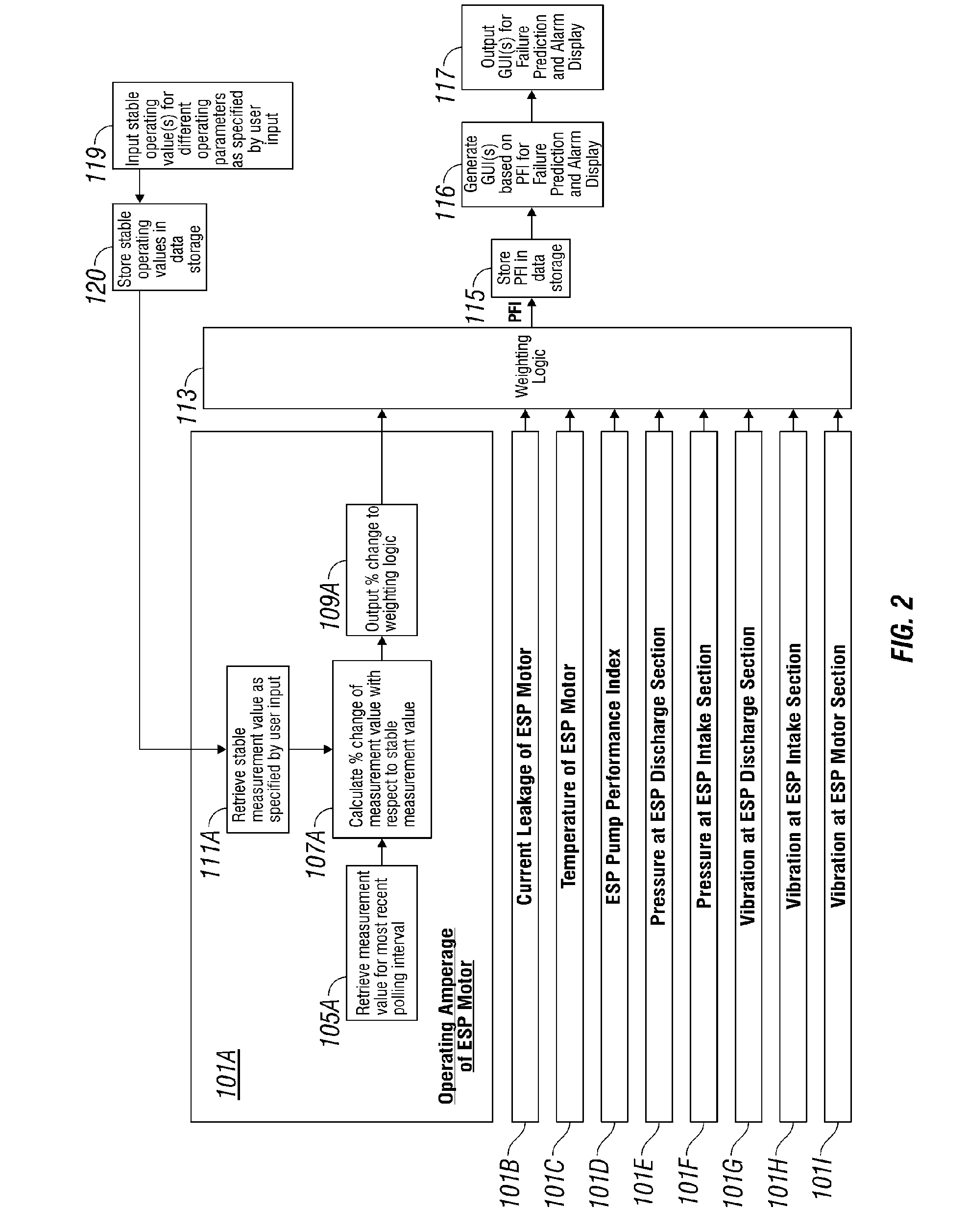
The present application relates to a system and method for real-time monitoring and failure prediction of electrical submersible pumps. The design includes generating a failure prediction value with a management system by calculating a percentage change of the respective first measurement values and the corresponding user-supplied stable operating values, the failure prediction value representing likelihood of failure of the electrical submersible pump.

Description

BACKGROUND OF THE INVENTION[0001]1. Field of the Invention[0002]This invention relates broadly to artificially lifted oil wells. More particularly, this invention relates to real-time monitoring and failure prediction of electrical submersible pumps.[0003]2. Description of Related Art[0004]In many oil wells, an artificial lift system is employed to lift fluid (e.g., petroleum) from a subterranean reservoir to a collection point. In many applications, the artificial lift system includes an electrical submersible pump that is positioned within a wellbore. The pump intakes fluid from the wellbore and pumps the fluid upwardly or laterally through the wellbore to the collection point. During extended operation, the components of the electrical submersible pump may be subject to degradation or breakage, which can lead to unwanted well intervention activities such as workovers.[0005]In many applications, the electrical submersible pumps are installed in wells that are offshore, subsea, or ...

Claims


Application Information

Patent Timeline
Patent Type & Authority Patents(United States)
IPC IPC(8): G01B21/00
CPCE21B47/0007F04D13/10E21B47/008F04D15/0088
Inventor FIELDER, LANCE I.
Owner SCHLUMBERGER TECH CORP
Learn More