Pneumatic tire and rim assembly with noise damper and pneumatic tire with noise damper

a technology which is applied in the field of assembly of pneumatic tires and rims, can solve the problems of easy peeling and easy peeling, and achieve the effects of preventing peeling of noise dampers, improving durability of noise dampers, and low air permeability

Inactive Publication Date: 2011-07-12
SUMITOMO RUBBER IND LTD
View PDF12 Cites 25 Cited by
  • Summary
  • Abstract
  • Description
  • Claims
  • Application Information

AI Technical Summary

Benefits of technology

[0017]The pneumatic tire-rim assembly of the present invention has the advantage that peeling of a noise damper is prevented and damages such as cracking liable to occur at circumferential both end portions of the noise damper is suppressed, so the durability of the noise damper can be drastically improvedDETAILED DESCRIPTION OF THE PREFERRED EMBODIMENTS
[0018]An embodiment of the present invention will now be explained with reference to the accompanying drawings.
[0019]FIG. 1 is a meridian section view illustrating a pneumatic tire-rim assembly 1 of this embodiment including a tire rotation shaft, FIG. 2 is a cross sectional view taken on line A-A in FIG. 1, and FIG. 3 is an enlarged cross sectional view of the tire.
[0020]The assembly 1 includes a rim 2, a pneumatic tire 3 attached to the rim 2, and a noise damper 4 which is disposed in a tire cavity “i” surrounded by the rim 2 and the tire 3 and extends in the circumferential direction of the tire.
[0021]In this embodiment, as the rim 2 is illustrated a so-called two piece wheel rim made of a metal comprising a rim body 2a on which bead portions 3b of the tire 3 are mounted, and a disk 2b supporting the rim body 2a and fixed to an axle. Of course, one piece rim and others can also be used. In this embodiment, normal rims prescribed in the standards mentioned above such as JATMA and the like are used.
[0022]The pneumatic tire 3 is, for example, a tubeless tire for passenger cars which include, as shown in FIGS. 1 and 3, a tread portion 3t, a pair of sidewall portions 3s, 3s radially inwardly extending from both edges of the tread portion 3t, and a pair of bead portions 3b, 3b disposed at radially inner edges of the sidewall portions. Thus, cavity-facing surface 3i of the tire is covered with an inner liner rubber having a low air permeability.

Problems solved by technology

A main cause of the road noise is considered a resonance vibration of air (cavity resonance) which generates in the tire cavity.
However, as a result of making a durability test on a tire assembly having the noise damper “a” by using a drum durability tester in further investigation of the present inventor, it was found that if the height H of the noise damper “a” is large, swaying or the like is easy to occur at the time of high speed running and, consequently, peeling may occur.

Method used


Image

  • Pneumatic tire and rim assembly with noise damper and pneumatic tire with noise damper
  • Pneumatic tire and rim assembly with noise damper and pneumatic tire with noise damper
  • Pneumatic tire and rim assembly with noise damper and pneumatic tire with noise damper

Examples


examples

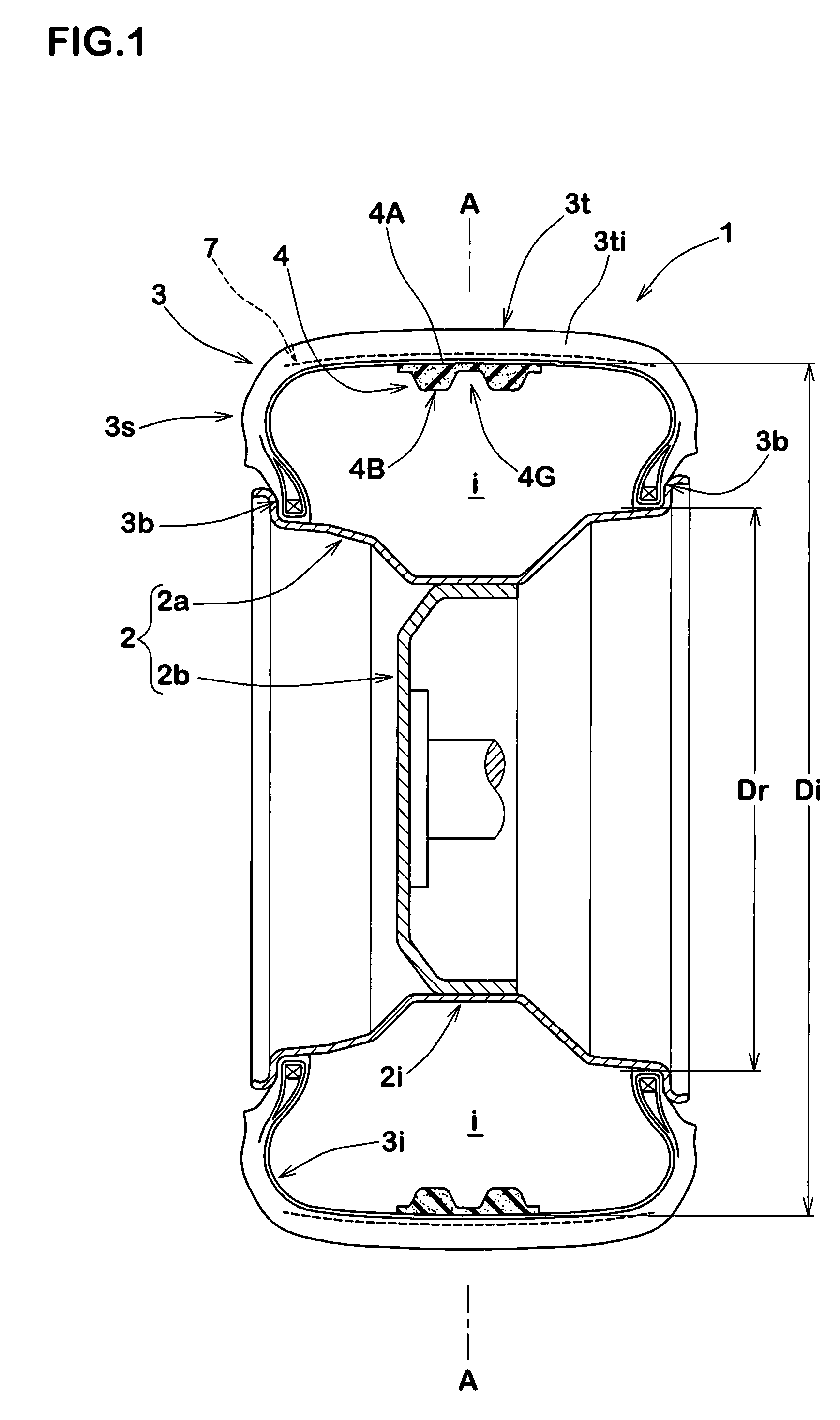
[0063]Tire assemblies having a basic structure shown in FIG. 1 were manufactured based on the specifications shown in Table 2. With respect to each assembly, the durability and road noise performance of the noise damper were tested. Other specifications common to all assemblies are as follows:[0064]Tire size: 195 / 65R15[0065]Rim size: 15×6JJ[0066]Whole volume V1 of tire cavity: 35,900 cm3 [0067]Noise damper

[0068]Sectional shape: symmetry as shown in FIG. 12 (provided that the basic size is shown in the table)

[0069]Circumferential length L: 1,850 mm

[0070]Angle of tapered portion: as shown in Table 2

Method for Fixing Noise Damper

[0071]A bar-like noise damper was curved along a tread region of the inner surface of the tire and adhered thereto using a pressure sensitive adhesive double-coated tape (“5000NS” made by Nitto Denko Corporation).

Adhesion Region in the Inner Surface of Tire: Finished to Smooth Surface

[0072]Manufacturers of spongy materials for noise damper shown in Table 2 are ...


PUM


Abstract

To reduce road noise in running by disposing a noise damper made of a spongy material in a cavity of a tire, a tire and rim assembly is provided. The tire and rim assembly 1 including a rim 2, a pneumatic tire 3 attached to the rim 2, and a noise damper 4 made of a spongy material which is disposed in a tire cavity “i” surrounded by the rim 2 and the pneumatic tire 3 and extends in the tire circumferential direction, wherein the noise damper 4 has a volume of 0.4 to 20% of the whole volume of the tire cavity “i” and is fixed to an inner surface 2i or 3i of the tire or rim, the noise damper 4 has a height of 30 mm or less from the inner surface, and the spongy material of the noise damper 4 has a hardness of 10 to 250 N, a tensile strength of 70 kPa or more and a specific gravity of 0.014 to 0.052.

Description

BACKGROUND OF THE INVENTION[0001]1. Technical Field[0002]The present invention relates to an assembly of a pneumatic tire and a rim, in which a noise damper made of a spongy material is disposed in a tire cavity to reduce a road noise generated during running.[0003]2. Background Art[0004]As one of tire noises is known a so-called road noise which sounds like “GHO” within a frequency range of 50 to 400 Hz when running on a road. A main cause of the road noise is considered a resonance vibration of air (cavity resonance) which generates in the tire cavity.[0005]In order to reduce such a road noise, it is proposed to dispose, as shown in FIG. 13(A), a noise damper “a” which is made of a spongy material and extends circumferentially, in a tire cavity “i” surrounded by a tire “b” and a rim “c”, thereby absorbing a resonance energy generated in the tire cavity “i” (cf. Patent Literature 1). In order to prevent the noise damper “a” from frequently colliding with the inner surface of the ti...

Claims


Application Information

Patent Timeline
Patent Type & Authority Patents(United States)
IPC IPC(8): B60C5/00B60C19/00
CPCB60C19/002Y10T152/10495B60C5/00B60C19/00
Inventor YUKAWA, NAOKI
Owner SUMITOMO RUBBER IND LTD
Why Eureka
Try Eureka