
Multi-signal analysis device

a multi-signal analysis and signal technology, applied in frequency-division multiplex, electrical control, instruments, etc., can solve the problems described below, achieve the effect of improving the efficiency of exhaust gas and fuel cell performance, and prolonging the delay tim

Inactive Publication Date: 2011-07-05
A&D CO LTD
View PDF11 Cites 4 Cited by
  • Summary
  • Abstract
  • Description
  • Claims
  • Application Information

AI Technical Summary

Benefits of technology

Enables effective comparison and analysis of signals in transient states, improving engine control and exhaust gas efficiency by eliminating time relation delays and revealing buried correlations within complex data sets.

Problems solved by technology

In this case, however, technical problems described below arise.

Method used


Image

  • Multi-signal analysis device
  • Multi-signal analysis device
  • Multi-signal analysis device

Examples


example

[0044]An example of the present invention will be described below in detail. FIG. 4 shows a layout view of sensors disposed in respective sections of an automobile, in which the multi-signal analyzer 1 of the present invention is used to analyze an automobile engine to thereby cause an ECU to perform an effective control. Since the detailed arrangement of the multi-signal analyzer 1 is as described above, the explanation thereof is omitted.

[0045]The sensors are disposed in the respective sections in the vicinity of the engine 51. More specifically, they include a fuel flow meter 55 disposed on a fuel tank 53, a torque sensor 59 disposed in the vicinity of a crank shaft 57 to detect the number of torque events, a tachometer 61 for detecting an engine speed, and an exhaust NOx sensor 65 for detecting an amount of NOx in the components of exhaust gas exhausted from a muffler 63.

[0046]Note that, in the example, although only the amount of NOx is detected in the components of the exhaust...


PUM


Abstract

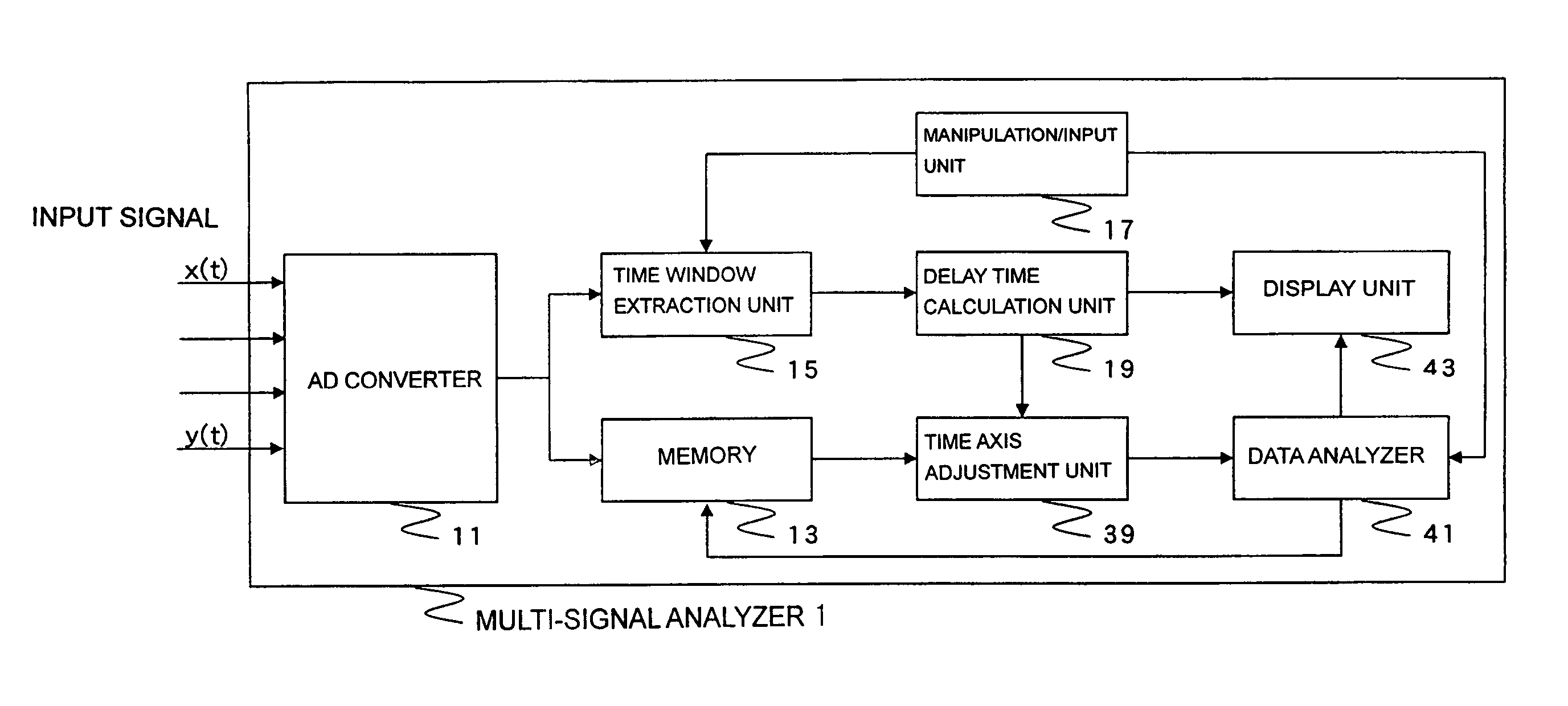
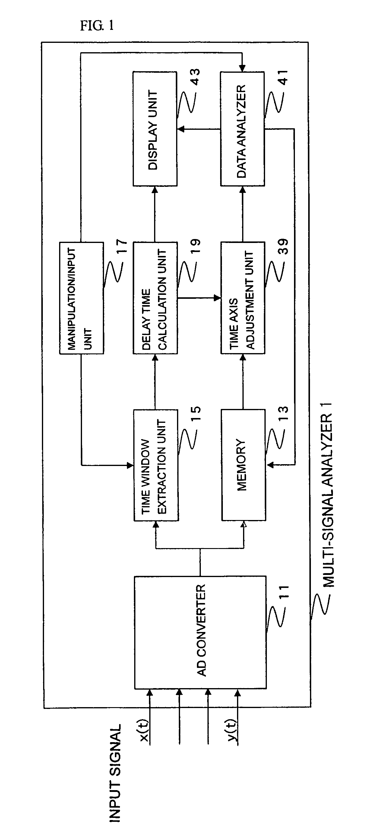
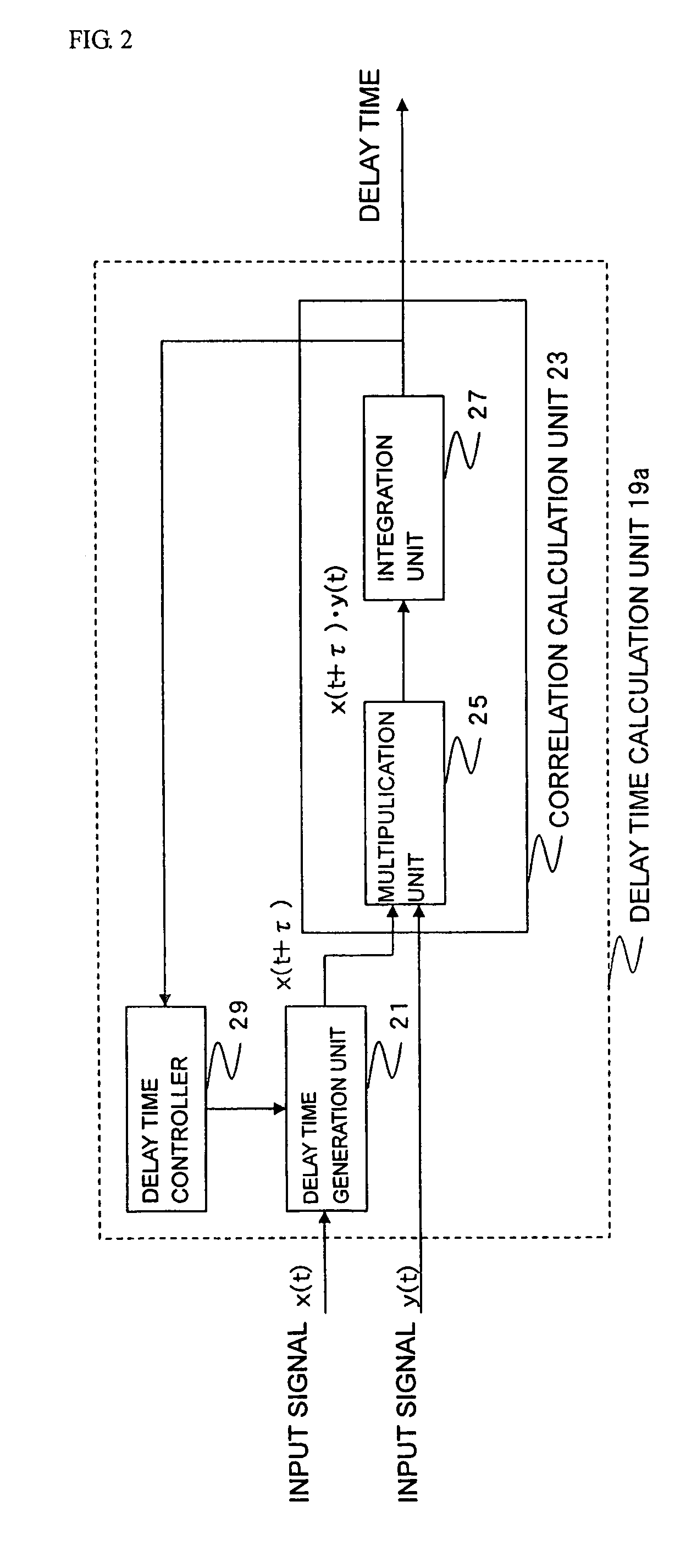
A multi-signal analyzer (1) includes an AD converter (11) for simultaneously receiving a plurality of time series signals representing physical and chemical phenomena and subjecting the signals to AD conversion, a delay time calculation unit (19) for calculating the delay time between arbitrary two signals x(1) and y(1) input to the AD converter (11), a time axis adjustment unit (39) for advancing or delaying the time axis of one of the arbitrary two signals according to the delay time calculated by the delay time calculation unit (19) to thereby make the two signals to have the same time axis, and a data analyzer (41) for performing analysis such as determining a mutual correlation coefficient for the two signals made to have the same time axis.

Description

TECHNICAL FIELD[0001]The present invention relates to a multi-signal analysis device (hereinafter, “multi-signal analyzer”), and more particularly, to a device for analyzing a correlation between a reference signal and a signal with a large delay time in comparison with the reference signal in a transient state.BACKGROUND ART[0002]Although the technical advance of an engine is indispensable as a background for supporting the development of an automobile industry, recently, regulations on exhaust emissions, which is made tighter than ever due to the effect of environmental problems, cause the automobile manufacturers of the respective countries to shift to design an engine for coping with a more strict regulation for environmental pollution.[0003]At present, an engine control technology in the main stream is an ECU (Engine Control Unit or Electric Control Unit). The ECU is of a microcomputer which precisely controles an amount of injected fuel, a timing of fuel injection, a timing of...

Claims


Application Information

Patent Timeline
Patent Type & Authority Patents(United States)
IPC IPC(8): G01R31/08F02D41/10F02D41/26G06F17/15
CPCF02D41/266G06F17/15F02D41/107Y02T10/47F02D2041/288F02D45/00G01D21/00F02D41/26
Inventor SUGITA, MITSUHARUURANO, YASUNORI
Owner A&D CO LTD
Learn More