
Differential-phase polarization-sensitive optical coherence tomography system

a tomography system and polarization-sensitive technology, applied in the field ofdifferential phase polarization-sensitive optical coherence tomography system, can solve the problems of reducing the detection sensitivity of the psoct, not having a fast axis angle in the setup, etc., and achieve the effect of high detection sensitivity and high speed

Inactive Publication Date: 2011-07-05
CHOU CHIEN
View PDF6 Cites 9 Cited by
  • Summary
  • Abstract
  • Description
  • Claims
  • Application Information

AI Technical Summary

Benefits of technology

The system achieves high-speed and high-sensitivity simultaneous measurement of reflectivity, phase retardation, and fast axis angle, improving detection sensitivity and accuracy without interference between phase retardation and fast axis angle images.

Problems solved by technology

However, the fast axis angle is not available in their setup. C. Hitzenberger et al.
However, a limited sampling rate in Hilbert transformation decreases detection sensitivity of the PSOCT.

Method used


Image

  • Differential-phase polarization-sensitive optical coherence tomography system
  • Differential-phase polarization-sensitive optical coherence tomography system
  • Differential-phase polarization-sensitive optical coherence tomography system

Examples


Embodiment Construction

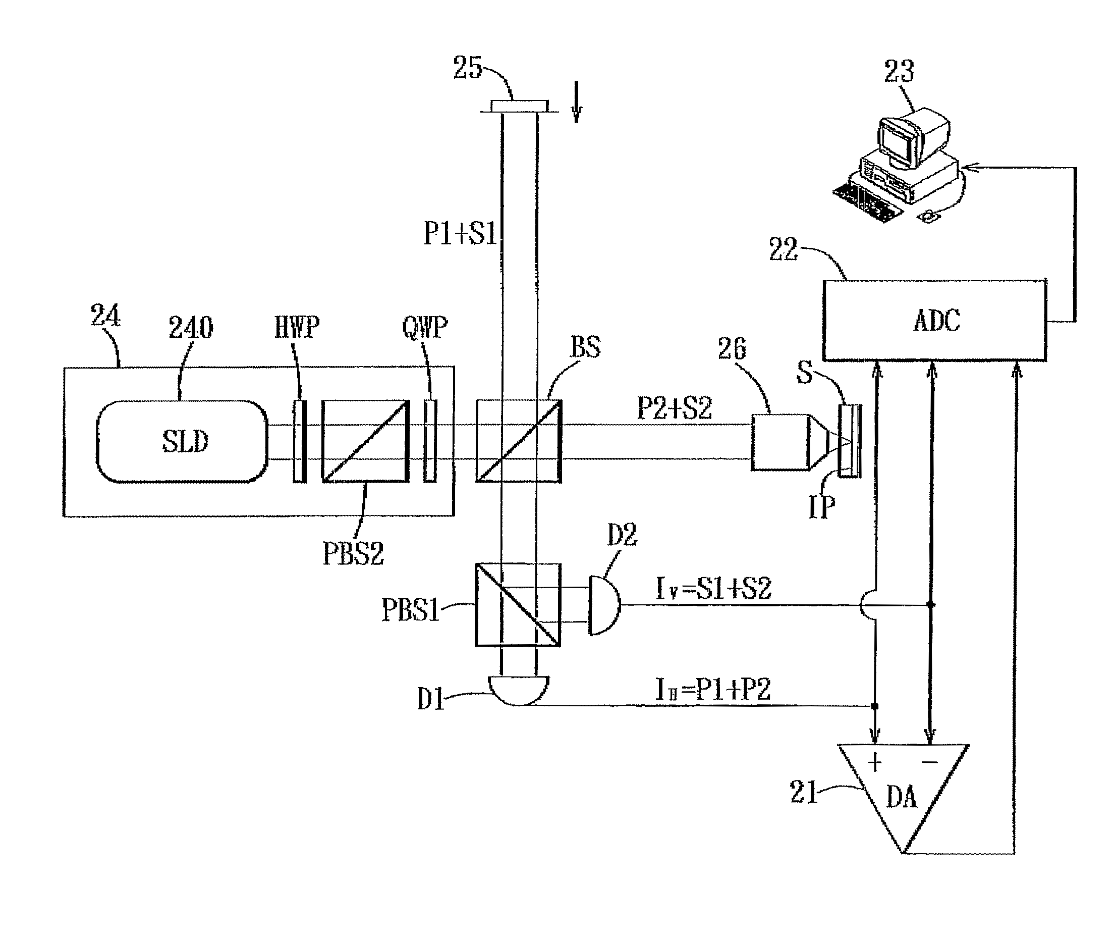
[0024]Referring to FIG. 1, the preferred embodiment of a differential-phase polarization-sensitive optical coherence tomography (DP-PSOCT) system according to the present invention is suitable for measuring optical characteristics of an anisotropic material or specimen (S), and includes a polarized heterodyne interferometer, a differential amplifier (DA) 21, a data acquisition unit 22 coupled to the differential amplifier 21, and a computing unit 23, such as a personal computer, coupled to the data acquisition unit 22. The polarized heterodyne interferometer includes a light source module 24, abeam splitter (BS), a movable mirror unit 25, a first polarization beam splitter (PBS1), a lens unit 26, and first and second photo detectors (D1, D2). The differential amplifier 21 and the data acquisition unit are both coupled to the first and second photo detectors (D1, D2). In this embodiment, the light source module 24 includes a broadband super luminescent diode (SLD) 240 employed as a l...


PUM


Abstract

A differential-phase polarization-sensitive optical coherence tomography system includes a polarized heterodyne interferometer for generating a reference beam to be reflected by a movable mirror unit, and a signal beam to be reflected by an imaging plane in a specimen. The interferometer further generates a first electrical signal output corresponding to first linear polarized waves of the reference and signal beams, and a second electrical signal output corresponding to second linear polarized waves of the reference and signal beams. A differential amplifier receives the first and second electrical signal outputs, and generates a differential signal output therefrom. A data acquisition unit is used to measure amplitudes of the first and second electrical signal outputs and the differential signal output. A computing unit computes the amplitudes measured by the data acquisition unit to determine a reflectivity, a phase retardation, and a fast axis angle of the imaging plane in the specimen.

Description

CROSS-REFERENCE TO RELATED APPLICATION[0001]This application claims priority of U.S. Provisional Patent Application No. 61 / 132,193, filed on Jun. 17, 2008.BACKGROUND OF THE INVENTION[0002]1. Field of the Invention[0003]The present invention relates to a differential-phase polarization-sensitive optical coherence tomography system that is capable of obtaining three tomographic images indicating a reflectivity, a phase retardation, and a fast axis angle of a specimen simultaneously.[0004]2. Description of the Related Art[0005]Phase retardation between P and S waves and the orientation angle of fast axis (hereinafter referred to as fast axis angle) are two parameters defining linear birefringence properties of anisotropic materials. K. Schoenenberger et al. (Applied Optics 37, pages 6026-6036, 1998) proposed the use of a circularly polarized laser beam in conventional polarization-sensitive optical coherence tomography (PSOCT) to obtain the phase retardation in terms of a ratio of demo...

Claims


Application Information

Patent Timeline
Patent Type & Authority Patents(United States)
IPC IPC(8): G01B9/02
CPCG01B9/02002G01B9/02091G01B2290/70G01B2290/45
Inventor CHOU, CHIEN
Owner CHOU CHIEN
Learn More