
Handoff control in an enterprise division multiple access wireless system

a wireless system and wireless network technology, applied in the field of wireless communication systems, can solve the problems of system capacity reduction, high cost, time-consuming, etc., and achieve the effect of convenient and flexible connectivity, less cost and easy and flexible connection

Inactive Publication Date: 2011-06-21
CISCO TECH INC
View PDF18 Cites 1 Cited by
  • Summary
  • Abstract
  • Description
  • Claims
  • Application Information

AI Technical Summary

Benefits of technology

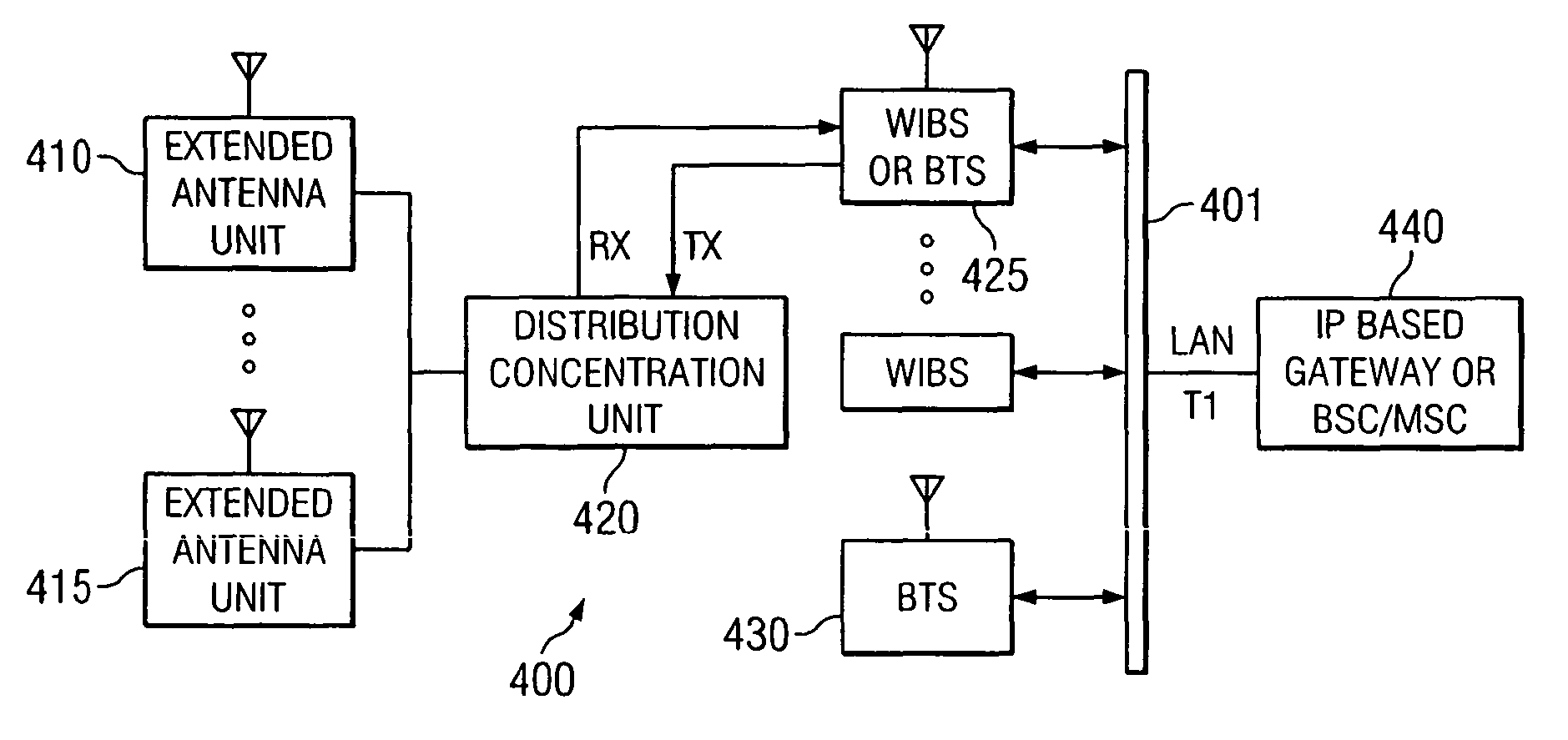
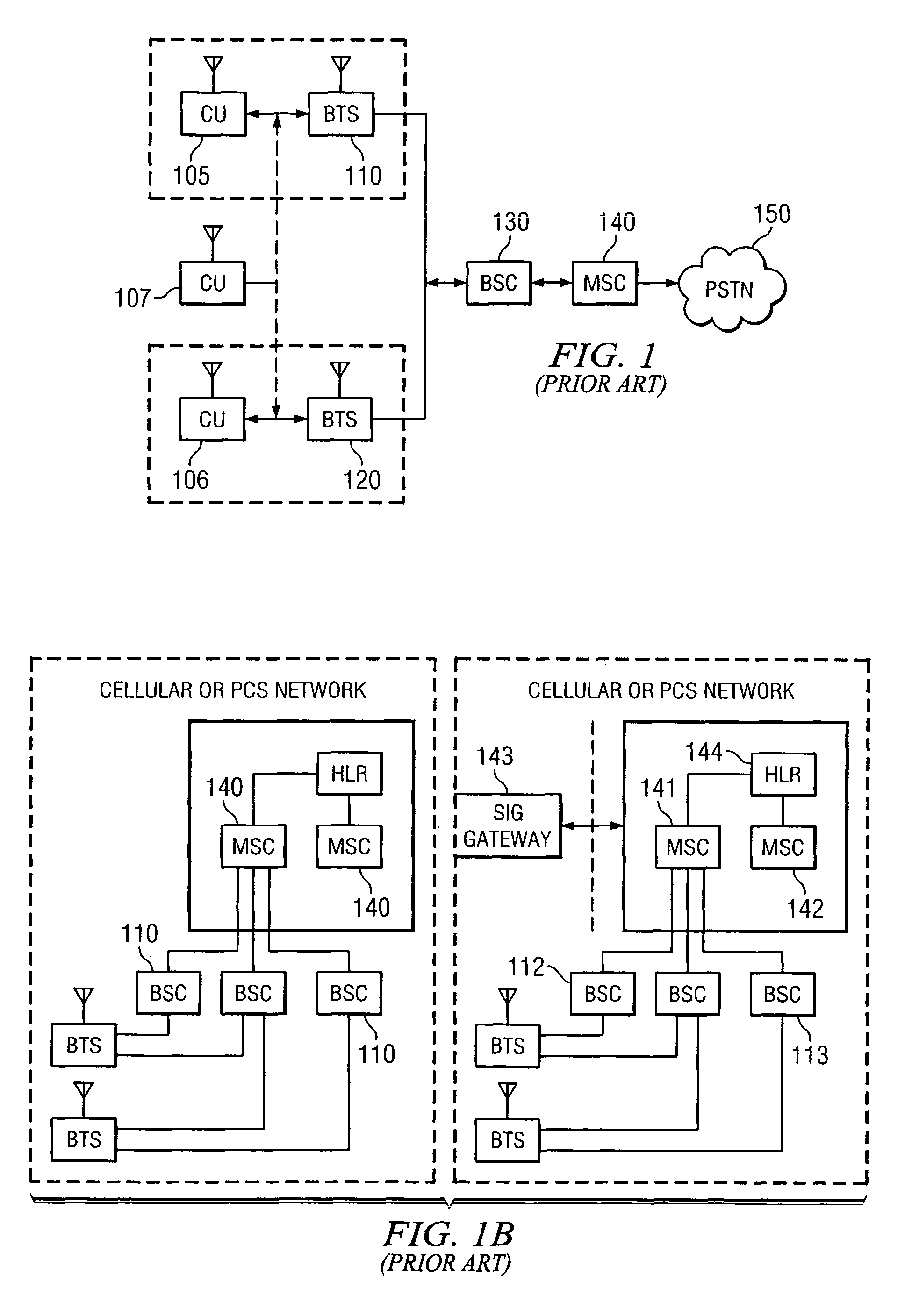
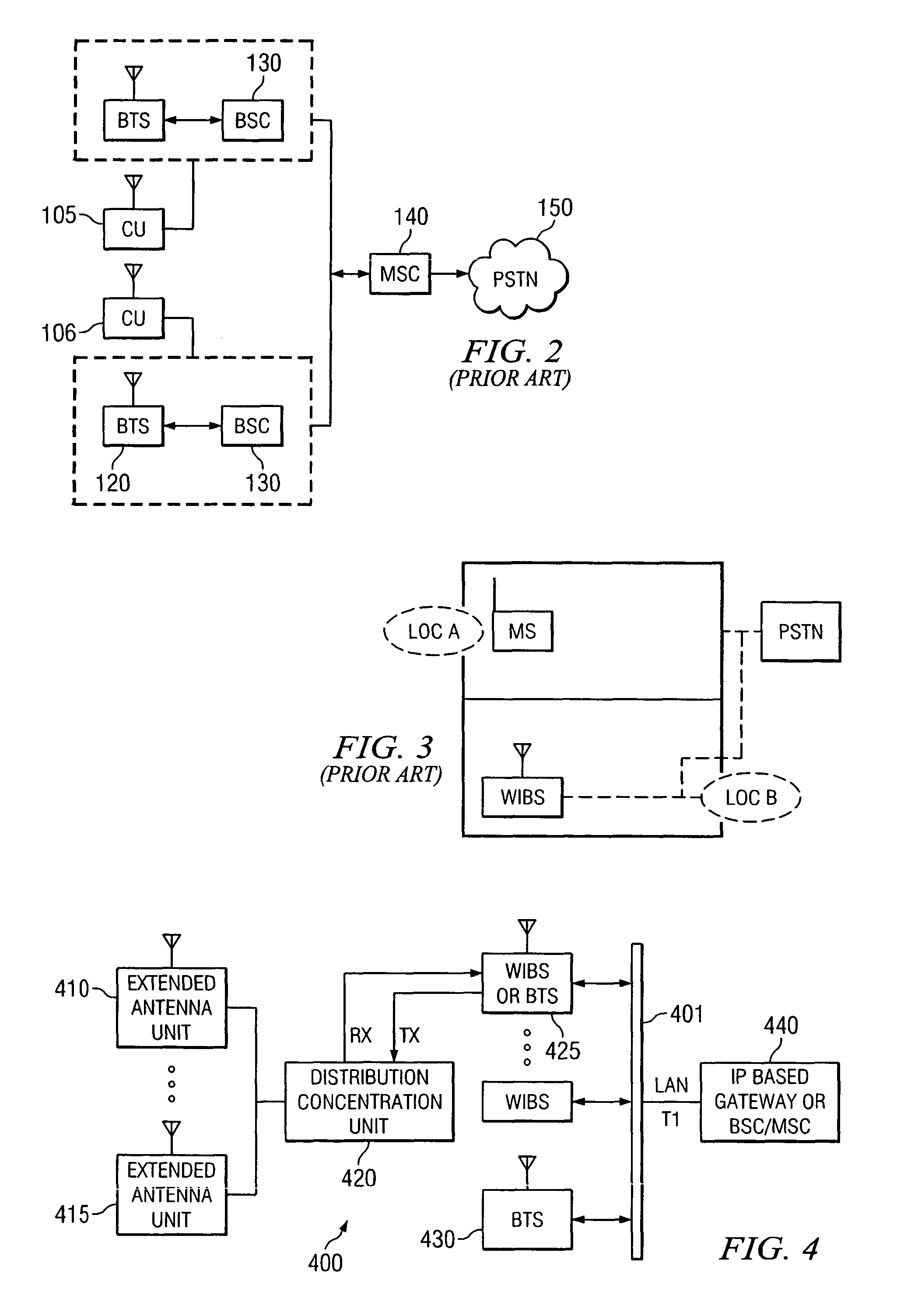
The present invention is a system and method for providing an enterprise in-building or campus-wide IP based CDMA wireless system. The invention allows for both voice and data transmission within the CDMA system without the delays and signal quality degradation encountered during call handoffs by conventional CDMA systems. The invention also controls handoffs between an enterprise CDMA communication system and external macro systems by keeping users on the enterprise premise, reducing costly and time-consuming handoffs. The invention includes a handoff technique that allows a mobile unit within the enterprise system to initiate a handoff, identifying the best new cell-site to which communications are to be transferred to and from an old cell-site. The invention also integrates wireless internet base station with existing networking infrastructure within an office building or campus, utilizing ethernet transmission protocols to transmit data over an ethernet back-bone to various wireless communication devices within a building. The invention further includes location based handoff control logic that determines a particular base station within the enterprise system serving a particular user and hands-off the user based on the signal delays inserted in the communication path between the user and the base station. The invention also allows inter-network communication between the wireless office communication system and other mobile networks on the Public Land Mobile Network (PLMN) using ethernet interface, which is less costly and flexible connectivity to existing in-office, building or campus networks.

Problems solved by technology

Such dedicated end-to-end connection can also be very expensive and time consuming.
If they are not balanced, system capacity may be reduced as the power control process is disturbed or the handoff region unreasonably expands.
The conventional system described in FIG. 1 or FIG. 2 does not allow each base station to communicate with the other during a handoff since all communications have to go through the base station controller.
This takes time and in a data traffic transmission can be costly.
However, in the system of FIG. 3, a common problem occurs when a mobile user enters a location that is near a border between two cell sites within the enterprise system.
This signal level fluctuation results in a ping-ponging situation in which repeated requests are made to handle calls back and forth between the two cell sites.
Furthermore, the ping-ponging situation raises the possibility that the call will be discontinued if it is unnecessarily transferred to a cell in which all channels are in use and thus unavailable for accepting the handoff.
Such unnecessary ping-ponging of handoffs increases the likelihood of the mobile unit incorrectly hearing handoff commands or failure in hearing commands.
This can be very costly and time consuming for a mobile user communicating with any other mobile user within the enterprise system.
Unnecessary ping-ponging handoffs also make it costly for the enterprise system accounting to reconcile calls within the enterprise system and those made to external cell sites.

Method used


Image

  • Handoff control in an enterprise division multiple access wireless system
  • Handoff control in an enterprise division multiple access wireless system
  • Handoff control in an enterprise division multiple access wireless system

Examples


Embodiment Construction

[0044]Reference will now be made in detail to the preferred embodiments of the invention, examples of which are illustrated in the accompanying drawings. While the invention will be described in conjunction with the preferred embodiments, it will be understood that they are not intended to limit the invention to these embodiments.

[0045]On the contrary, the invention is intended to cover alternatives, modifications and equivalents, which may be included within the spirit and scope of the invention as defined by the appended claims. Furthermore, in the following detailed description of the present invention, numerous specific details are set forth in order to provide a thorough understanding of the present invention. However, it will be obvious to one of ordinary skill in the art that the present invention may be practiced without these specific details. In other instances, well known methods, procedures, components, and circuits have not been described in detail as not to unnecessari...


PUM


Abstract

A wireless office communication system including a wireless internet base station (WIBS) encompassing a base station controller, a mobile switch controller and an ethernet interface module for coupling the WIBS to an existing internet protocol (IP) based network. A wireless office communication system can also be based on the conventional architecture comprising the BTS, BSC and MSC. The WIBS or BTS is attached to a number of antennas via different and identifiable delay elements for the purpose of determining the serving antennas of mobile communication units. A location determination logic enables the system to handle handoffs between a WIBS or BTS and the external public communication system in an optimum manner. Handling handoff requests in this manner prevents unnecessary ping-ponging of handoff and can also increase the percentage of successful handoff by frequency monitoring of the quality of the mobile communication units located in the handoff transition area, particularly to the public communication system.

Description

CROSS-REFERENCE TO RELATED APPLICATION[0001]This application is a continuation of U.S. application Ser. No. 09 / 655,102, filed Sep. 5, 2000 now U.S. Pat. No. 6,901,061 by Ki Hyun Joo et al. and entitled “Handoff Control in an Enterprise Division Multiple Access Wireless System”.FIELD OF THE INVENTION[0002]The present claimed invention relates generally to the field of wireless communication systems. More particularly, the present claimed invention relates to handoff control between code division multiple access communication systems within an in-door enterprise system and with the public system.BACKGROUND ART[0003]Communication systems that utilize coded communication signals are well known in the art. One such system is a code division multiple access (CDMA) cellular Communication system such as set forth in the Telecommunications Industry Association / Electronic Industries Association International Standard (TIA / EIA IS-95), hereinafter referred to as IS-95. In accordance with the IS...

Claims


Application Information

Patent Timeline
Patent Type & Authority Patents(United States)
IPC IPC(8): H04W4/00H04B7/216
CPCH04W4/04H04W64/00H04W36/38H04W36/08H04W36/00837H04W36/087
Inventor JOO, KI HYUNRHA, PETER S.KANG, CHOL SUHYUN, SANG KYOON
Owner CISCO TECH INC
Learn More