
Wireless camera flash trigger device

a remote flash device and camera technology, applied in the field of wireless camera flash trigger devices, can solve the problems of poor ambient lighting conditions, digital camera models do not provide for the disablement of the built-in flash and wireless connection of the remote flash device, and achieve the effect of convenient use, convenient use, and convenient us

Inactive Publication Date: 2011-06-21
DOWNEY ROBERT M 55 +1
View PDF1 Cites 25 Cited by
  • Summary
  • Abstract
  • Description
  • Claims
  • Application Information

AI Technical Summary

Benefits of technology

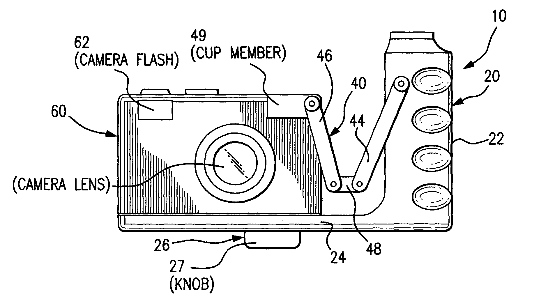
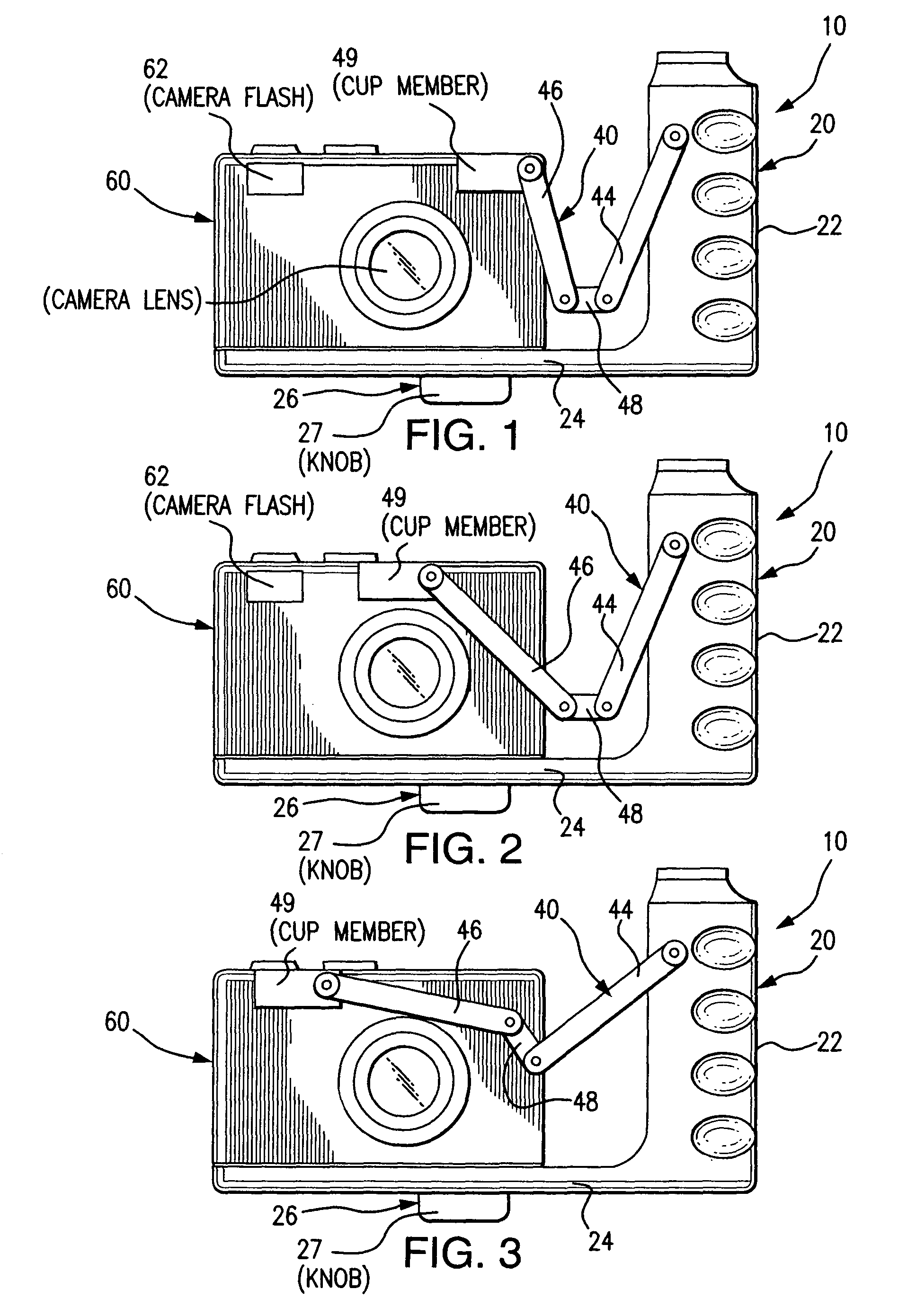
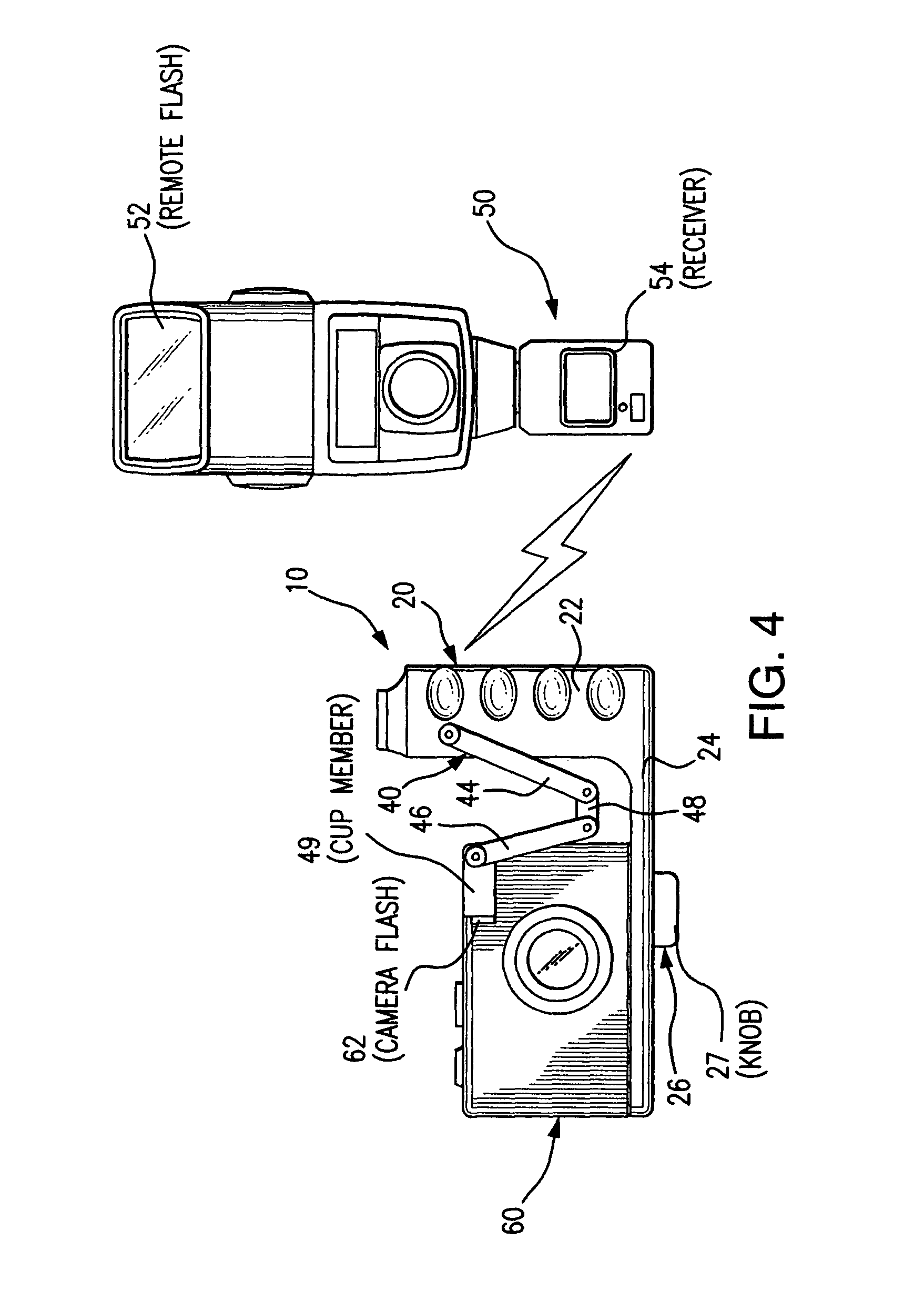
"The present invention is a flash accessory device that can be attached to most compact digital cameras. It includes a hand grip with a detector circuit, a wireless transmitter, and a battery power source. An arm assembly extends from the hand grip and can be adjusted to position a flash sensor in front of the camera's built-in flash. A cup member surrounds the flash sensor to block the light emitted by the built-in flash. The sensor detects the light from the built-in flash and triggers the wireless signal to activate the remote flash in synchronization with the built-in flash. The sensor is programmable to detect different pre-flash sequences in different camera models. The technical effect of this invention is to provide a convenient and adaptable flash accessory for compact digital cameras."

Problems solved by technology

Notwithstanding the high resolution capability of compact digital cameras, there are times when the light provided by the built-in electronic flash of the camera is less than adequate for taking a professional quality photograph.
This can be a result of poor ambient lighting conditions, undesirable shadows and reflections, or the subject being beyond the illuminating capability of the camera flash.
However, presently available compact digital camera models do not provide for disablement of the built-in flash and wireless connection of a remote flash device.
Thus, this device is not universally adaptable to other camera models and it is not wireless.

Method used


Image

  • Wireless camera flash trigger device
  • Wireless camera flash trigger device
  • Wireless camera flash trigger device

Examples


Embodiment Construction

[0031]The flash accessory device is shown throughout the several views of the drawings and is generally indicated as 10. The flash accessory device 10 is adapted for use with most compact digital camera models and is structured for wireless activation of a remote flash 52 in synchronization with activation of a built-in flash 62 of the compact digital camera 60 while blocking the light emitted by the built-in camera flash 62. The flash accessory device 10 includes a hand grip 20 with a handle portion 22 and a mounting base 24. The mounting base 24 attaches to the bottom a compact digital camera 60 using the standard ¼ inch tripod socket on the bottom of the camera and a threaded fastener 26 comprised of a screw thread shaft and a turning knob 27 on the end of the shaft. The handle portion 22 of the hand grip 20 contains a multi-mode digital pre-flash detector circuit 30, a wireless transmitter 32 and a battery power source 34.

[0032]An articulating arm assembly 40 extends from the ha...


PUM


Abstract

A flash accessory device readily adaptable to most compact digital camera models provides a hand grip with a mounting base for attachment to the bottom of a compact digital camera. The hand grip contains a multi-mode digital pre-flash detector circuit, a wireless transmitter and a battery power source. An articulating arm extends from the hand grip and is adjustably movable relative to the front of the camera in order to position a sensor on the end of the articulating arm directly in front of the camera's built-in flash. A cup member surrounding the sensor covers the built-in flash to block light emitted by the built-in flash. Light from the built-in flash is detected by the sensor which triggers transmission of a wireless signal from the transmitter to a receiver in a remote flash device to thereby activate illumination of the remote flash in synchronization with activation of the built-in camera flash.

Description

BACKGROUND OF THE INVENTION[0001]1. Field of the Invention[0002]The present invention relates to camera flash accessory devices and, more particularly, to an apparatus for triggering operation of a remote flash in synchronization with activation of a built-in flash of a compact digital camera while blocking the light emitted by the built-in camera flash.[0003]2. Discussion of the Related Art[0004]Flash devices have long been used in the field of photography for casting light onto the subject of a photograph at the moment the camera shutter opens to take the photograph. In most instances, the camera flash is located on or directly adjacent to the camera. For many years, cameras have been made to include a hot shoe for removably attaching an electronic flash accessory device that is triggered in synchronization with the shutter operation of the camera. Other camera models have a built-in electronic flash, including compact digital cameras that have been increasing in popularity in rec...

Claims


Application Information

Patent Timeline
Patent Type & Authority Patents(United States)
IPC IPC(8): H04N5/222
CPCH04N5/2256H04N23/56
Inventor NIBLOCK, KEVIN
Owner DOWNEY ROBERT M 55
Learn More