Class D audio amplifier

a technology of audio amplifier and output signal, applied in the direction of amplifiers, dc amplifiers with modulator-demodulator, semiconductor devices/discharge tubes, etc., can solve the problems of affecting the modulation depth of output signal, the output signal of the amplifier to have a greater modulation depth than, and the output signal to have a greater modulation depth. , to achieve the effect of improving clipping recovery

Active Publication Date: 2011-06-21
GOODIX TECH HK CO LTD
View PDF17 Cites 12 Cited by
  • Summary
  • Abstract
  • Description
  • Claims
  • Application Information

AI Technical Summary

Benefits of technology

[0011]An advantage of the class D amplifier according to the invention is that any integrator that may be part of the feedback loop remains in its normal operating range, providing a much improved clipping recovery. Furthermore, any bootstrap capacitor that may be present in the amplifier for generating the pulse width modulated output signal is recharged regularly.
[0013]As mentioned above, the clipping control unit, that is preferably located near the input of the amplifier, is designed for limiting the duty cycle of the pulse width modulated output signal by controlling the duty cycle of the input signal. Although this may be achieved in various ways, it is preferred that the clipping control unit is arranged for receiving an output indicator signal indicative of the output signal, and for delaying a transition of the input signal until the output indicator signal has responded to a previous transition of the input signal. In this way, it is assured that the output signal will keep changing sign. Effectively the pulse width of the input signal is adjusted to the minimum value resulting in a sign change of the output signal.
[0020]The present invention further provides a method of driving a class D amplifier capable of receiving a digital input signal and in which the output signal is fed back to shape pulses, the method comprising the step of limiting the duty cycle of the pulse width modulated output signal by controlling the input signal.

Problems solved by technology

However, the gain of the feedback loop influences the modulation depth of the output signal.
This may cause the output signal of the amplifier to have a greater modulation depth than the input signal.
Ultimately, the increased modulation depth may cause the output signal to clip to the supply voltage and stop changing sign.
A class D amplifier is typically slow to recover from this condition, and the demodulated output signal may initially be distorted when the duty cycle returns to normal operating values.
Although the arrangement of U.S. Pat. No. 6,577,186 operates well, its use is limited to class D amplifiers having a clock generator.
In addition, this Prior Art solution effectively forces the output to change sign but still allows the integrators to run away, thus only offering a partial solution to the problem.

Method used


Image

  • Class D audio amplifier
  • Class D audio amplifier
  • Class D audio amplifier

Examples


Embodiment Construction

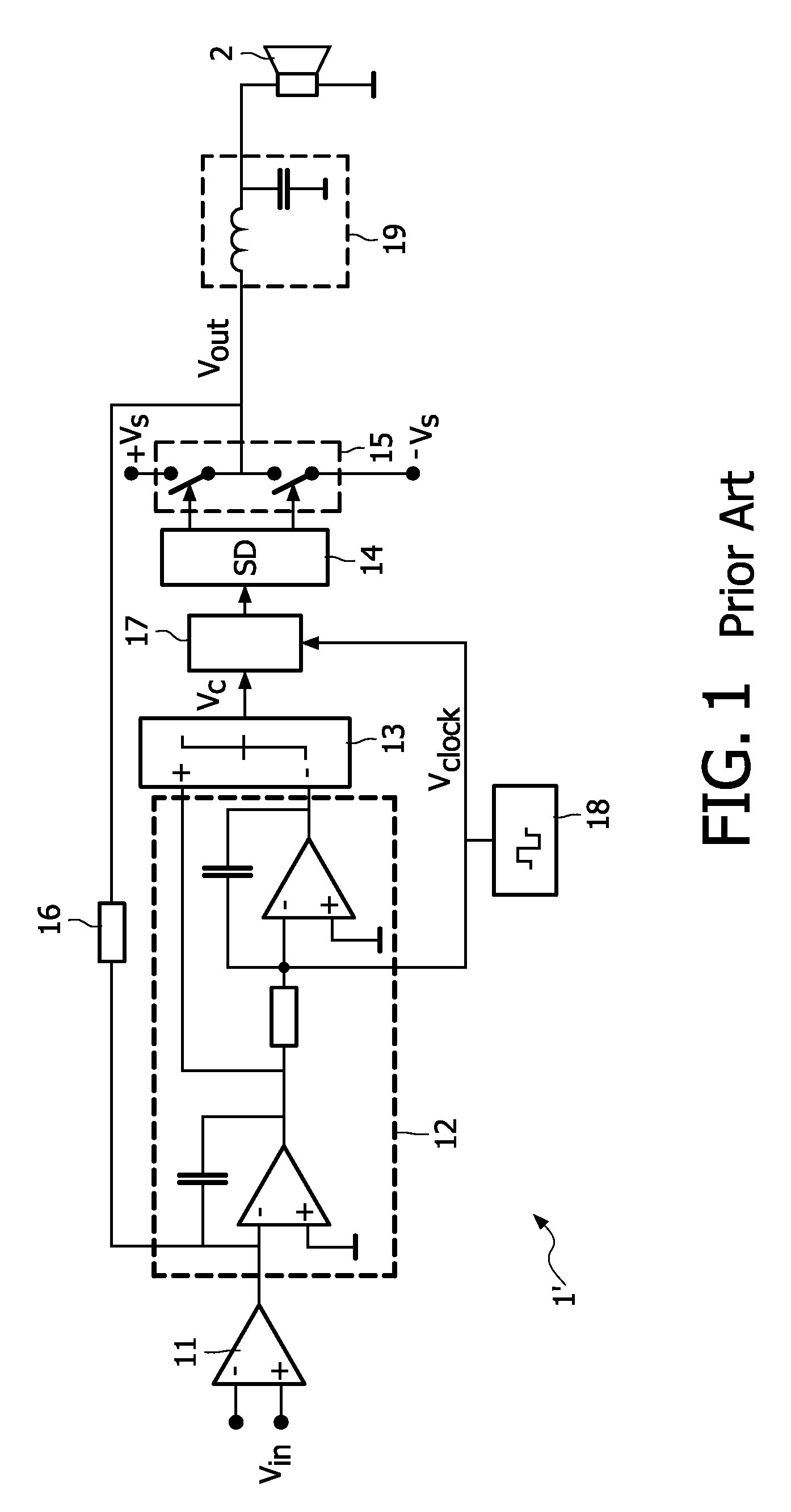
[0031]The Prior Art class D amplifier 1′ shown in FIG. 1 comprises an input unit 11, a pulse shaping unit 12, a comparator unit 13, a driver unit 14, a switching output unit 15, a feedback resistor 16, a pulse width modulation limiter 17, and an oscillator (clock pulse generator) 18. The output of the amplifier 1′ is coupled to a demodulation filter 19, which in turn is coupled to a loudspeaker 2. The amplifier 1′ is discussed in more detail in U.S. Pat. No. 6,577,186 mentioned above.

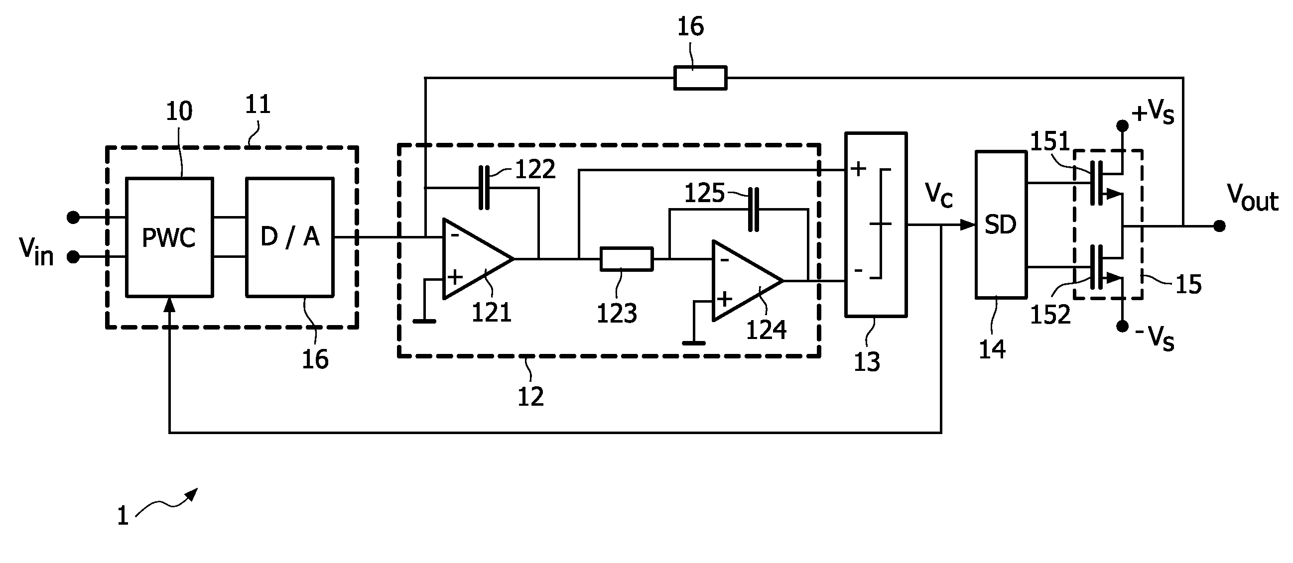
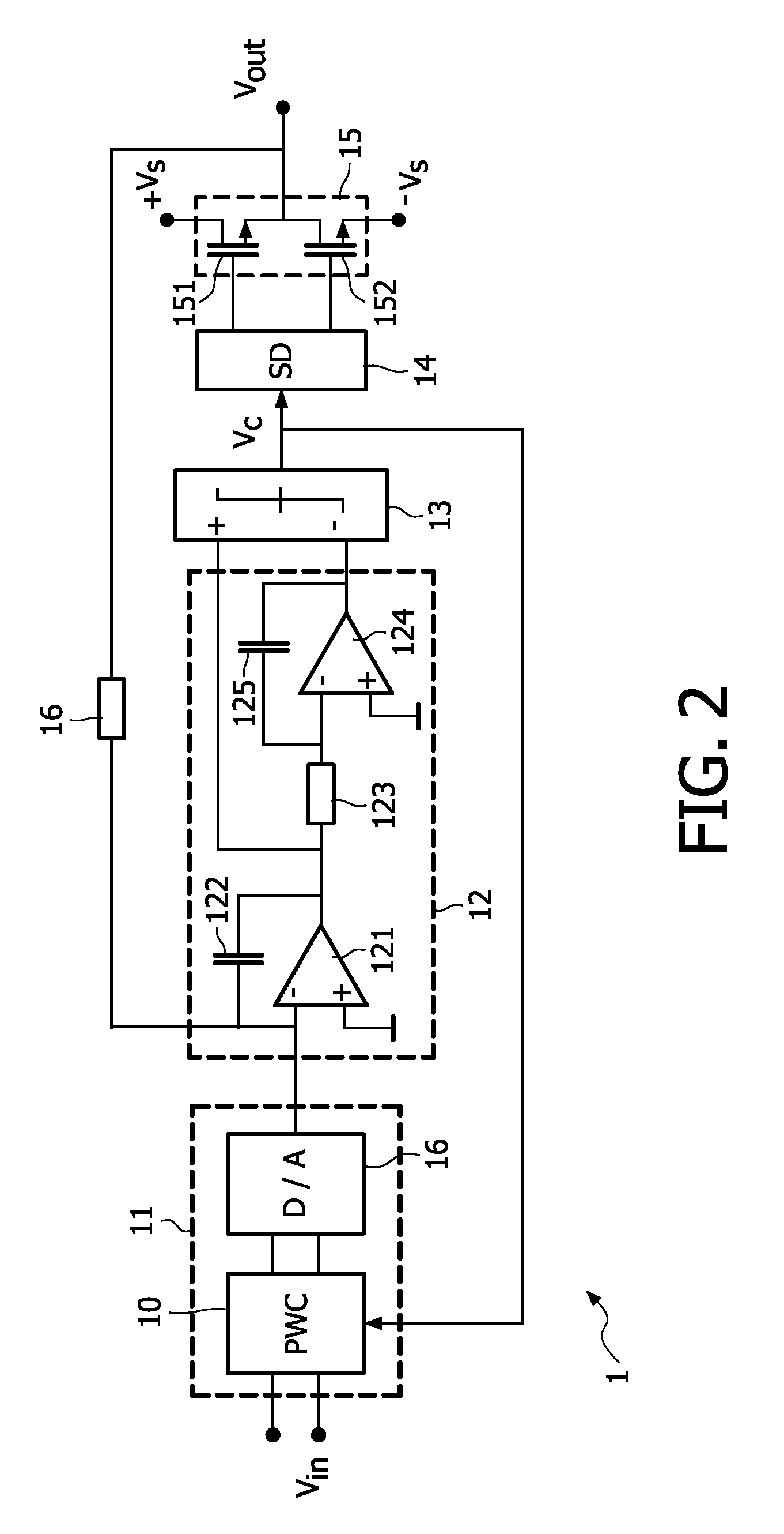
[0032]In the amplifier 1′ the input unit 11 converts an analog input voltage into an analog input current. The pulse width modulation unit 12 comprises two integrators, each constituted by an opamp and a capacitor, the output of each integrator being coupled to a respective input of the comparator unit 13. A clock signal generated by the oscillator 18 is fed to the input of the second integrator.

[0033]Between the comparator unit 13 and the driver unit 14 a pulse width modulation limiter 17 is interposed...


PUM


Abstract

A class D amplifier (1) comprises an input unit (11) for receiving a digital input signal (Vin), a pulse shaping unit (12) for producing pulse shaped signals in dependence of the input signal (Vin), a comparator unit (13) for comparing the pulse shaped signals and producing a comparator signal, a driver unit (14) for producing driver signals in dependence of the comparator signal, a switching output unit (15) for producing a pulse width modulated output signal (Vout) in dependence of the driver signals, and a feedback unit (16) for feeding the output signal (Vout) back to the pulse shaping unit (12). The input unit (11) comprises a clipping control unit (10) for controlling the duty cycle of the pulse width modulated output signal (Vout).

Description

FIELD OF THE INVENTION[0001]The present invention relates to an audio amplifier. More in particular, the present invention relates to a class D amplifier which is capable of producing a pulse width modulated output signal.BACKGROUND OF THE INVENTION[0002]In a class D amplifier, the output stage is used as a switch for switching the output signal between a positive and a negative supply voltage in dependence of an input signal. The resulting output signal is therefore a pulse width modulated bipolar signal which may be demodulated by a demodulation filter and then be made audible by a loudspeaker.[0003]The switching of the output stage typically switches one transistor of a pair of output transistors on while switching the other transistor off. When one of the output transistors is off, its current and hence its power dissipation are zero, resulting in a high efficiency, and relatively low power and cooling requirements.[0004]Class D amplifiers are typically provided with an integrat...

Claims


Application Information

Patent Timeline
Patent Type & Authority Patents(United States)
IPC IPC(8): H03F1/04
CPCH03F3/217H03G11/008H03F2200/345H03F2200/66H03F2200/78H03F2200/351
Inventor DOOPER, LUTSENBERKHOUT, MARCO
Owner GOODIX TECH HK CO LTD
Why Eureka
Try Eureka