
Systems and methods for graphically displaying and analyzing call treatment operations

Active Publication Date: 2011-06-14
SECURUS TECH LLC
View PDF9 Cites 45 Cited by
  • Summary
  • Abstract
  • Description
  • Claims
  • Application Information

AI Technical Summary

Benefits of technology

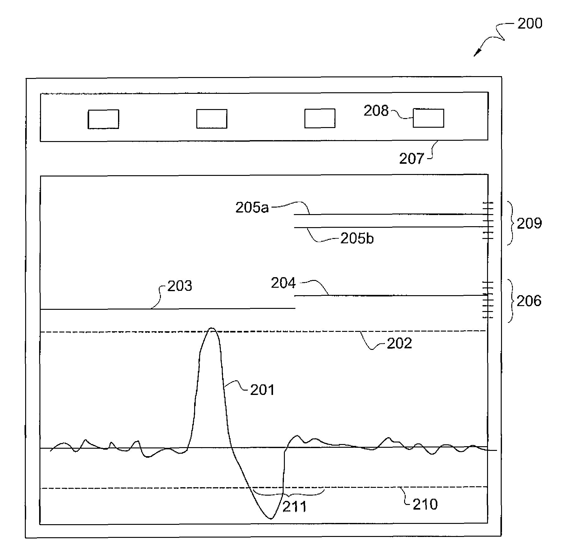
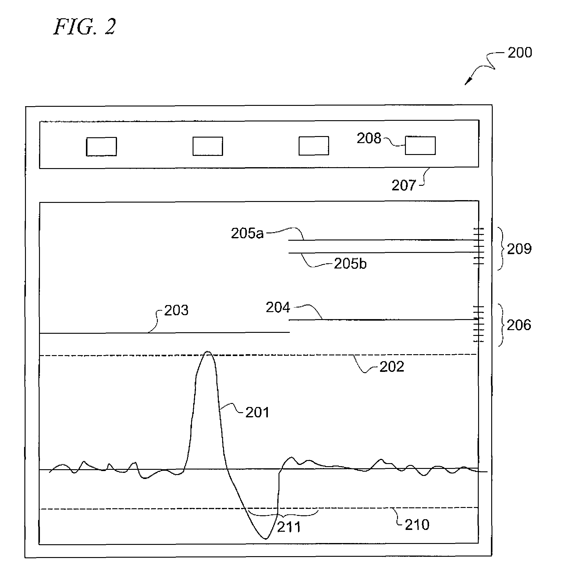
[0007]The display may include an interface for viewing and modifying algorithm parameters. For example, graphical representations of the settings for determining an event may be visually depicted so that a user may readily see how those settings correspond to the telephone call signal as represented by the aforementioned waveform. Accordingly, a technician may change the operation of the algorithm to optimize performance by changing the parameters within the display and readily visualize their effect on the operation if the algorithm with respect to the telephone call signal.

Problems solved by technology

In that case, since an outside line is already established, the challenge becomes enabling the call processing system to recognize three-way calls from outside lines and disconnect the call in response thereto.
This can create a problem when an inmate makes a collect call to a party.
However, the prison call processing system may mistake this accept signal for a three-way event and disconnect the call before the conversation begins.
It is a challenge for call processing system designers to program the systems to distinguish between hook flashes and other sounds, such as dirty keypads.
In addition to dirty keypads, other phenomena result in low accuracy for event-detection algorithms.
For example, noises caused by the telephone system itself switching the caller from a recorded message to a connected conversation may fool the system into detecting a false event.
Currently, it is difficult for a technician or administrator to debug or set-up a system because the data that is analyzed by the system is often not saved.
Further, current systems are embodied in hardware, often in specialized boards that do not offer ways to view the operation in real time.
In fact, users are usually limited, at most, to inspecting the debug registers of the board's processor.
Thus, debugging or setting up a system is often time consuming and frustrating because of a lack of available and convenient information for the technician.
Further, owners of the system (and potential customers) may not be able to satisfy themselves of proper operation because of the same lack of information.

Method used


Image

  • Systems and methods for graphically displaying and analyzing call treatment operations
  • Systems and methods for graphically displaying and analyzing call treatment operations
  • Systems and methods for graphically displaying and analyzing call treatment operations

Examples


Embodiment Construction

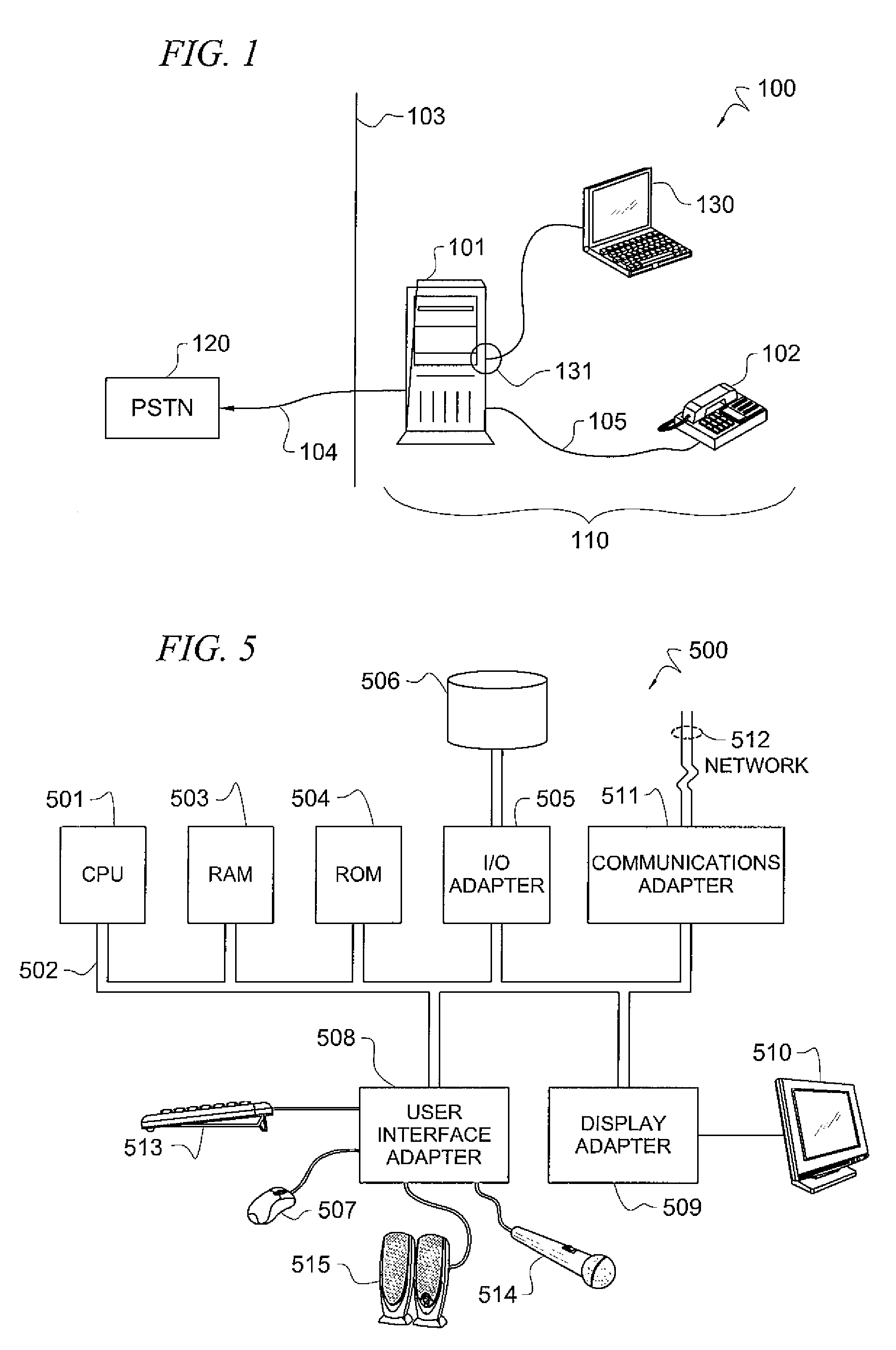
[0017]FIG. 1 is an illustration of system 100 that includes graphical display system 130 adapted according to one embodiment of the invention. Graphical display system 130 is depicted as a computer in FIG. 1, but is more accurately described (in some embodiments) as a program that may be run on a computer and receives data from an analyzing algorithm in unit 101 and displays a representation of the signals on telephone line 104 / 105 and a representation of the results of the analyzing algorithm. A more detailed description of the interface of graphical display system 130 is included in the description of FIG. 2, below. Output 131 allows graphical display system 130 to connect to unit 101 and receive data from the call event detection algorithm operable thereon.

[0018]System 100 includes telephone system 110 that is connected to Public Switched Telephone Network (PSTN) 120 through line 104. Boundary 103 separates telephone system 110 from PSTN 120 and may be considered to conceptually ...


PUM


Abstract

A system and method for graphically demonstrating a call-processing operation include receiving data representing signals in a telephone call and data from an event-detecting algorithm, the data from the event-detecting algorithm describing an operation of the algorithm on the telephone call, and generating a graphical display including a waveform based on the data representing signals in the telephone call and a graph of the operation of the event-detection algorithm.

Description

TECHNICAL FIELD[0001]The present invention relates generally to systems for controlling phone access in a variety of institutions.BACKGROUND OF THE INVENTION[0002]In some call processing systems, it may be desirable to detect the occurrence of events, such as three-way calling events, as may be invoked by a remote calling party and / or may be attempted to be hidden from a call processing system. For example, in prison call processing systems, prisoners are often forbidden from calling some parties, i.e., judges, victims, witnesses, and the like. Accordingly, some prisons have adopted call processing systems that use a list of allowed and / or disallowed telephone numbers for individual prisoners and / or all prisoners collectively. When an inmate attempts to call a forbidden number or a number which is not an allowed number, the prison call processing system does not set up a call. To avoid the call processing system blocking such calls, some inmates have attempted to call an outside par...

Claims


Application Information

Patent Timeline
IPC IPC(8): H04M3/00H04M3/42
CPCH04M3/38H04M3/385H04M2203/6054H04M2203/5027H04M3/568
Inventor MCFARLEN, CHRISTOPHER R.
Owner SECURUS TECH LLC
Learn More