
System and method of detecting fluid and leaks in thermal treatment system basins

a technology of thermal treatment system and fluid detection, which is applied in the field of thermal treatment system, can solve the problems of compromising sterile conditions, complicated procedures, and high flammability of glycol or other thermal transfer medium, and achieves the effect of reducing the risk of contamination, and reducing the detection efficiency

Inactive Publication Date: 2011-06-14
MICROTEK MEDICAL
View PDF116 Cites 30 Cited by
  • Summary
  • Abstract
  • Description
  • Claims
  • Application Information

AI Technical Summary

Benefits of technology

The present invention relates to a thermal treatment system that includes a drape for collecting a sterile medium. The drape has a sensing device that detects the presence of liquid or leaks and sends signals to control system operation. The system also includes a fuse that limits the drape to a single use to maintain sterility. The technical effects of the invention include detecting and controlling drape conditions, ensuring sterility of drapes for medical procedures, and preventing drape reuse for safety purposes.

Problems solved by technology

Additionally, the glycol or other thermal transfer medium is highly flammable or toxic and, in any event, complicates the procedure.
The Faries, Jr. et al. patent (U.S. Pat. No. 5,163,299) notes that scraping congealed liquid from the drape is undesirable in view of the potential for damage to the drape, resulting in a compromise of sterile conditions.
Although this hand manipulation is somewhat effective, it is not optimal, and often is inconvenient and constitutes an additional chore for operating room personnel.
However, when insignificant amounts of liquid are present within a thermal treatment system basin, the system heating and cooling mechanisms operate with minimal thermal resistance, thereby enabling the mechanisms to become damaged.
Further, the drapes employed by the system may be damaged by being disposed proximate the heating or cooling mechanism without having the liquid to absorb the thermal energy.
Since only sterile drapes are to be used during surgical procedures, a leak in a surgical drape compromises sterility and contaminates the entire surgical procedure, thereby increasing the risk of injury to a patient.
Further, the drape is required to be placed on the system with the plug aligned with a corresponding plug receptacle for system operation, thereby restricting the manners in which the drape may be positioned on the system to form the drape container.
Thus, the system may continually operate in the presence of a drape container leak until personnel notice and respond to the leak indication, thereby increasing the risk of contamination of a surgical procedure and damage to the system heating or cooling mechanism when a drape leak occurs.

Method used


Image

  • System and method of detecting fluid and leaks in thermal treatment system basins
  • System and method of detecting fluid and leaks in thermal treatment system basins
  • System and method of detecting fluid and leaks in thermal treatment system basins

Examples


Embodiment Construction

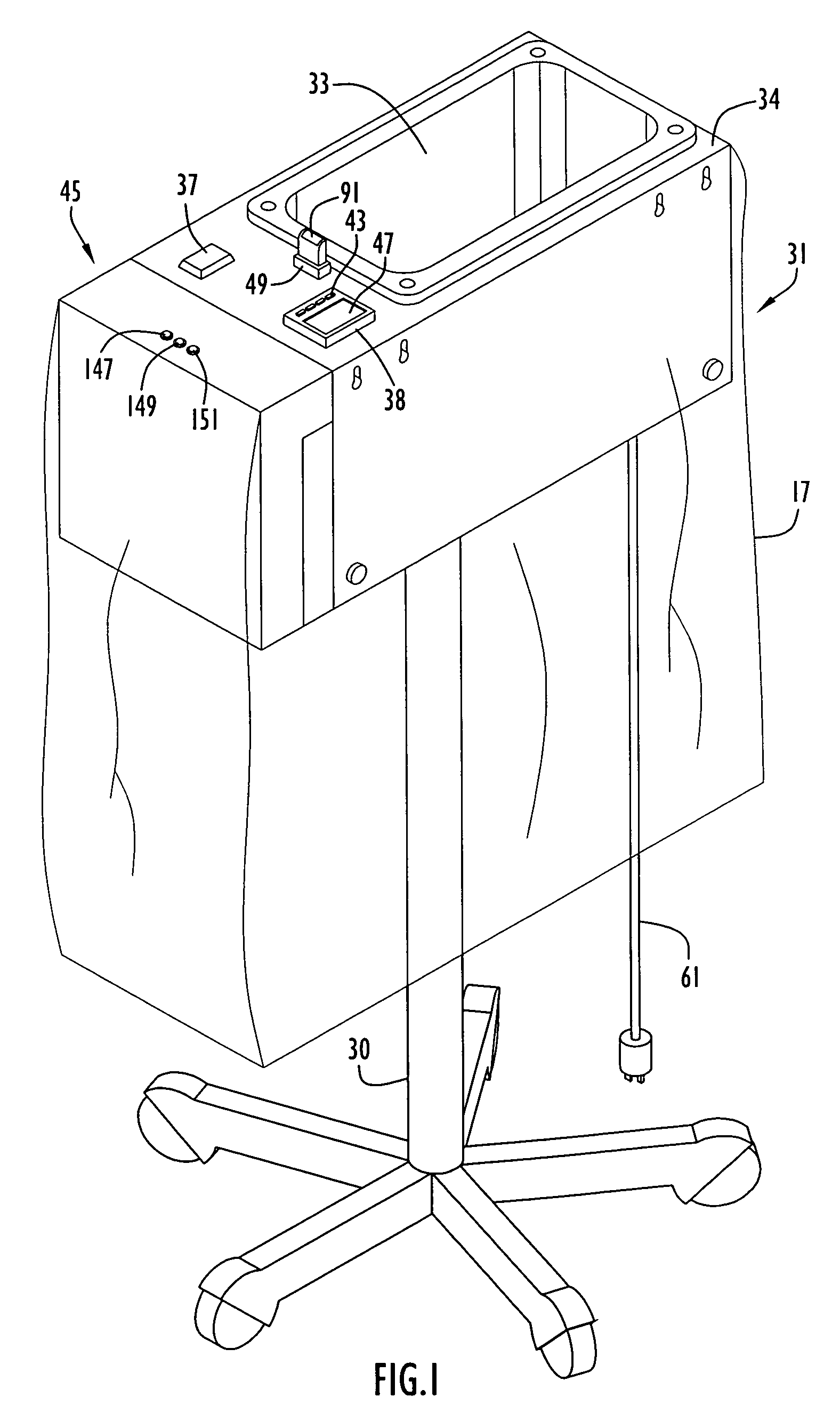
An exemplary thermal treatment system and drape to heat a sterile medium (e.g., solution or liquid) and detect drape container conditions according to the present invention is illustrated in FIG. 1. Specifically, the system includes a cabinet or housing 31, a wiring housing 45 attached to the cabinet and a warming basin 33 recessed into a cabinet top surface 34. The cabinet or housing may be disposed on a stand 30, preferably including casters or rollers for transport, or be utilized on a table or counter top. Basin 33 may be of any shape; however, by way of example only, the basin is illustrated as being substantially rectangular. A power switch 37 and a temperature controller / indicator 38 are provided on top surface 34 adjacent basin 33 and toward wiring housing 45. The wiring housing is attached to the cabinet side wall that is closest to power switch 37 and facilitates connections as described below. A receptacle 49 is disposed on top surface 34 between the power switch and temp...


PUM

PropertyMeasurementUnit
voltageaaaaaaaaaa
supply voltageaaaaaaaaaa
reference voltageaaaaaaaaaa

Abstract

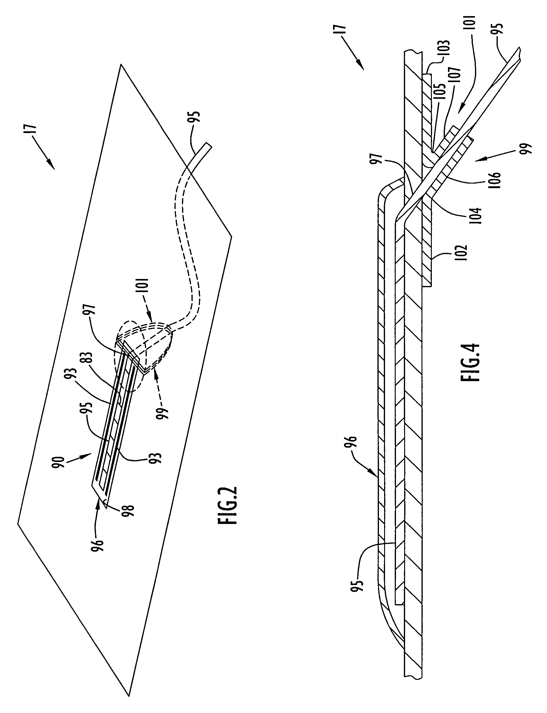
A drape including a sensing device according to the present invention is disposed over a top surface of a thermal treatment system having a basin recessed therein. A portion of the drape is pushed down into the basin to form a drape container for collecting a sterile medium. The thermal treatment system may be of the type that either heats or congeals the sterile medium. The sensing device includes electrodes that are typically disposed through the drape and sealed. The electrodes provide signals indicating the presence of liquid and / or leaks or other conditions within the drape container to the system to facilitate control of system operation. In addition, the sensing device includes a fuse to limit the drape to a single use. The system disables the fuse to indicate prior use and detects tampering to bypass the fuse, thereby preventing use of the drape for subsequent medical procedures.

Description

BACKGROUND OF THE INVENTION1. Technical FieldThe present invention pertains to thermal treatment systems. In particular, the present invention pertains to detection of the presence of solution and / or leaks within a drape container of a thermal treatment system basin. The thermal treatment system thermally treats a sterile surgical liquid placed within the drape container and may be of the types disclosed in U.S. Pat. No. 4,393,659 (Keyes et al.), U.S. Pat. No. 4,934,152 (Templeton), U.S. Pat. No. 5,163,299 (Faries, Jr. et al.), U.S. Pat. No. 5,331,820 (Faries, Jr. et al.), U.S. Pat. No. 5,333,326 (Faries, Jr. et al.), U.S. Pat. No. 5,400,616 (Faries, Jr. et al.), U.S. Pat. No. 5,402,644 (Faries, Jr. et al.), U.S. Pat. No. 5,429,801 (Faries Jr. et al.), U.S. Pat. No. 5,457,962 (Faries, Jr. et al.), U.S. Pat. No. 5,502,980 (Faries, Jr. et al.), U.S. Pat. No. 5,522,095 (Faries, Jr. et al.), U.S. Pat. No. 5,524,643 (Faries, Jr. et al.), U.S. Pat. No. 5,551,240 (Faries, Jr. et al.), U.S....

Claims


Application Information

Patent Timeline
Patent Type & Authority Patents(United States)
IPC IPC(8): A61L2/24
CPCA61B19/081A61F7/0085A61B2017/0023G01N31/226A61B2019/4873A61B2019/025A61B50/13A61B46/10A61B2090/0814
Inventor FARIES, JR., DURWARD I.HEYMANN, BRUCE R.BLANKENSHIP, CALVINHENDRIX, DAVID
Owner MICROTEK MEDICAL
Learn More