
Passive optical network system and ranging method

a technology of optical network and ranging method, which is applied in the field of passive optical network system and ranging method, can solve problems such as spoiling the economy of pon system, and achieve the effects of reducing utilization bandwidth, excellent economy, and high degree of techniqu

Inactive Publication Date: 2011-06-07
HITACHI LTD
View PDF23 Cites 9 Cited by
  • Summary
  • Abstract
  • Description
  • Claims
  • Application Information

AI Technical Summary

Benefits of technology

The present invention provides a WDM-PON system with improved ranging efficiency and economics. The system includes an OLT, optical fibers, an optical splitter, and a plurality of ONUs. The OLT includes a burst receiver circuit dedicated to ranging and a WDM filter that discriminates received signals separately for ranging. The system also includes a table for managing the received amplitudes and phases of the ONUs. The use of a dedicated wavelength for ranging reduces the number of expensive burst receiver circuits required. The system also includes a ranging window for performing ranging procedures, but the ranging window is set to open for a short time to avoid wasting bandwidth. The system also includes a WDM filter that discriminates received signals separately for ranging, and a burst receiver circuit dedicated to ranging. The use of a dedicated wavelength for ranging and the inclusion of a burst receiver circuit dedicated to ranging in the uplink wavelengths helps to decrease the loss of bandwidth attributed to ranging. The system also includes means for measuring the amplitudes and phases of received signals and managing the received amplitudes and phases of the ONUs. Overall, the system provides improved ranging efficiency and economics, and the activation time of the ONUs is shortened.

Problems solved by technology

Therefore, the inclusion of the burst receiver circuits in the number of the uplink wavelengths might spoil the economy of the PON system.

Method used


Image

  • Passive optical network system and ranging method
  • Passive optical network system and ranging method
  • Passive optical network system and ranging method

Examples


Embodiment Construction

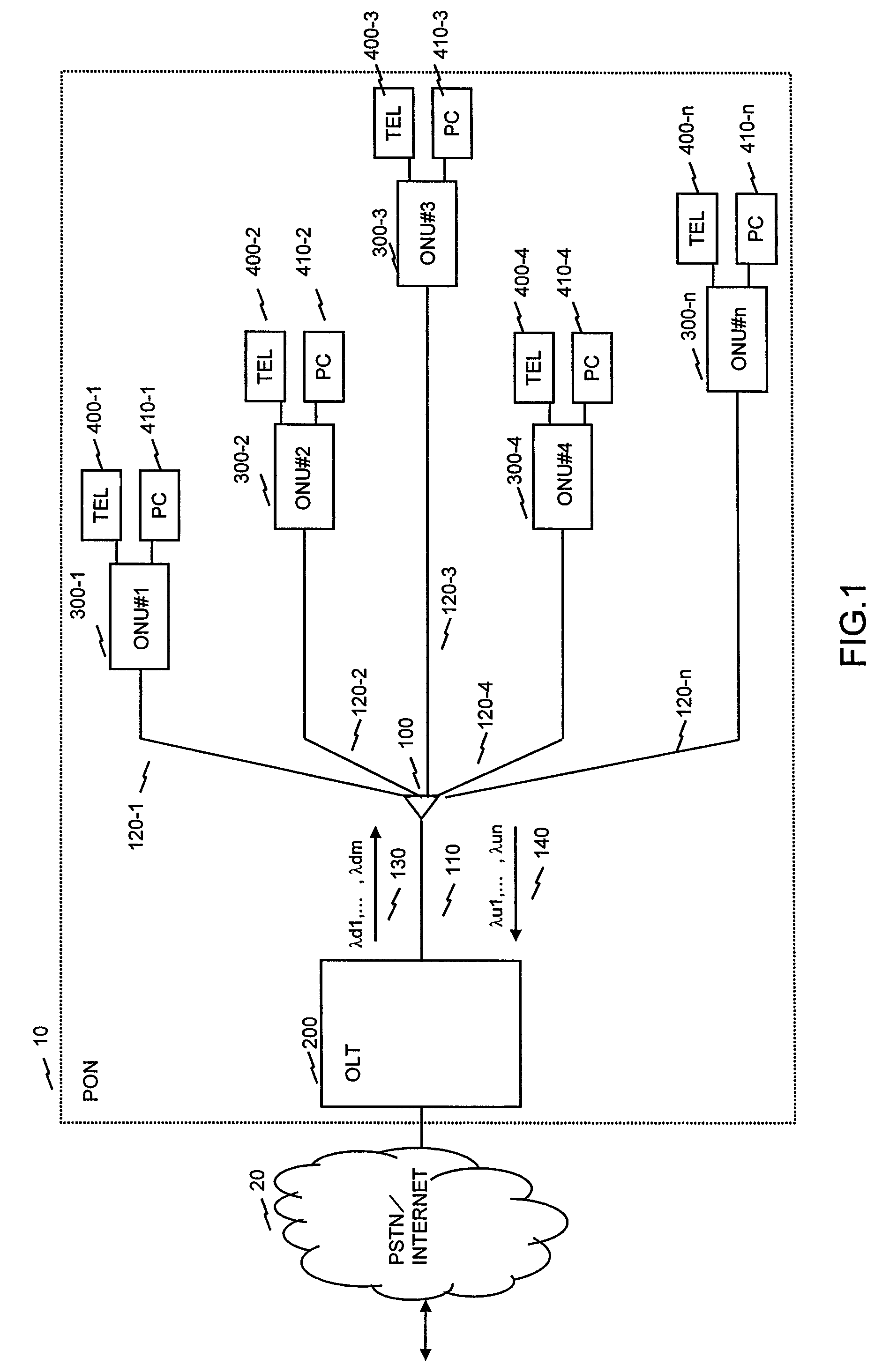
[0068]FIG. 1 shows the configuration of an optical access network.

[0069]A PON 10 is connected to a PSTN / Internet 20 so as to transmit and receive data. The PON 10 includes, for example, an optical splitter 100, a main line fiber 110, branch line fibers 120, an OLT 200 and a plurality of ONUs 300. Further, the PON 10 may well include telephone sets 400 and personal computers 410 which are connected to the corresponding ONUs 300. Incidentally, although the ONUs 300 may well be ONTs, they shall be described as the ONUs in this embodiment.

[0070]The ONUs 300 numbering, for example, 32 can be connected to the OLT 200 through the single main line fiber 110, the optical splitter 100 and the branch line fibers 120. In the example of FIG. 1, five ONUs are illustrated, and their fiber lengths from the OLT 200 are respectively different. In the illustrated example, the ONU 300-1 is 1 km in terms of the fiber length from the OLT 200, the ONU 300-2 is 10 km in terms of the fiber length from the O...


PUM


Abstract

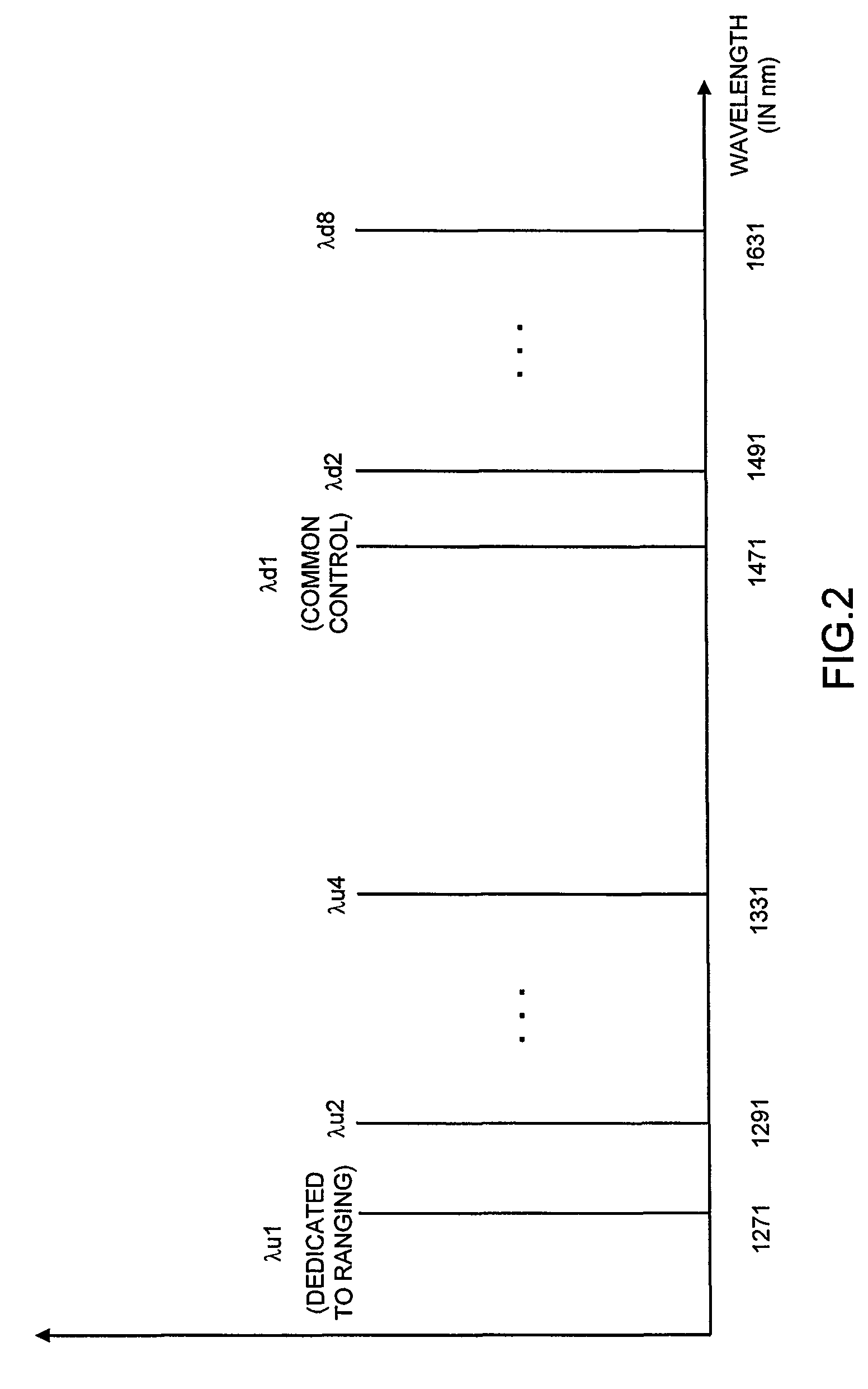
In a WDM-PON system wherein a plurality of ONUs transfer signals by sharing wavelengths, one wavelength dedicated to a ranging procedure is set, and the ranging is performed with only the dedicated wavelength, so as to measure reciprocating delay times. At the other wavelengths, transmission signals from a plurality of ONUs are transferred in time division multiplexing based on the obtained reciprocating delay times. An OLT includes a burst receiver circuit for only the wavelength dedicated to the ranging, and subsequently to the ranging, the OLT adjusts transmission amplitudes and transmission phases for the ONUs, so as to equalize received amplitudes and received phases in the OLT. For this purpose, the OLT includes means for measuring the amplitudes and phases of received signals, as the burst receiver circuit, and it includes a table for managing the received amplitudes and received phases of the respective ONUs.

Description

BACKGROUND OF THE INVENTION[0001]The present invention relates to a passive optical network system and a ranging method. More particularly, it relates to a passive optical network system in which communications are performed by wavelength division multiplexing and time division multiplexing in a passive optical network “PON” wherein a plurality of subscriber connection devices share an optical transmission line, and a ranging method in the passive optical network system.[0002]A Passive Optical Network (PON) includes an Optical Line Termination (OLT), and a plurality of Optical Network Units (ONUs) or Optical Network Terminations (ONTs). Signals from terminals (PCs etc.) connected to the ONUs are sent to the OLT in such a way that the optical signals are optically multiplexed on an optical fiber leading to the OLT, through the ONUs, optical fibers and an optical splitter. After the OLT has executed various signal processes, communications from the terminals of certain ones of the ONU...

Claims


Application Information

Patent Timeline
Patent Type & Authority Patents(United States)
IPC IPC(8): H04B10/00H04B10/077H04B10/27H04B10/272H04J14/00H04J14/02H04J14/08
CPCH04J14/0282H04J3/0682
Inventor KAZAWA, TOHRUYAJIMA, YUSUKEOOHIRA, MASAKI
Owner HITACHI LTD
Learn More