Lens array, LED head, exposure device, image forming apparatus and reading apparatus
an exposure device and led head technology, applied in the field of lenses array, led head, exposure device, image forming apparatus and reading apparatus, can solve the problems of insufficient resolution, phenomenon (called flare) where light from an object reaches an imaging plane without being collected,
- Summary
- Abstract
- Description
- Claims
- Application Information
AI Technical Summary
Benefits of technology
Problems solved by technology
Method used
Image

Examples
embodiment 1
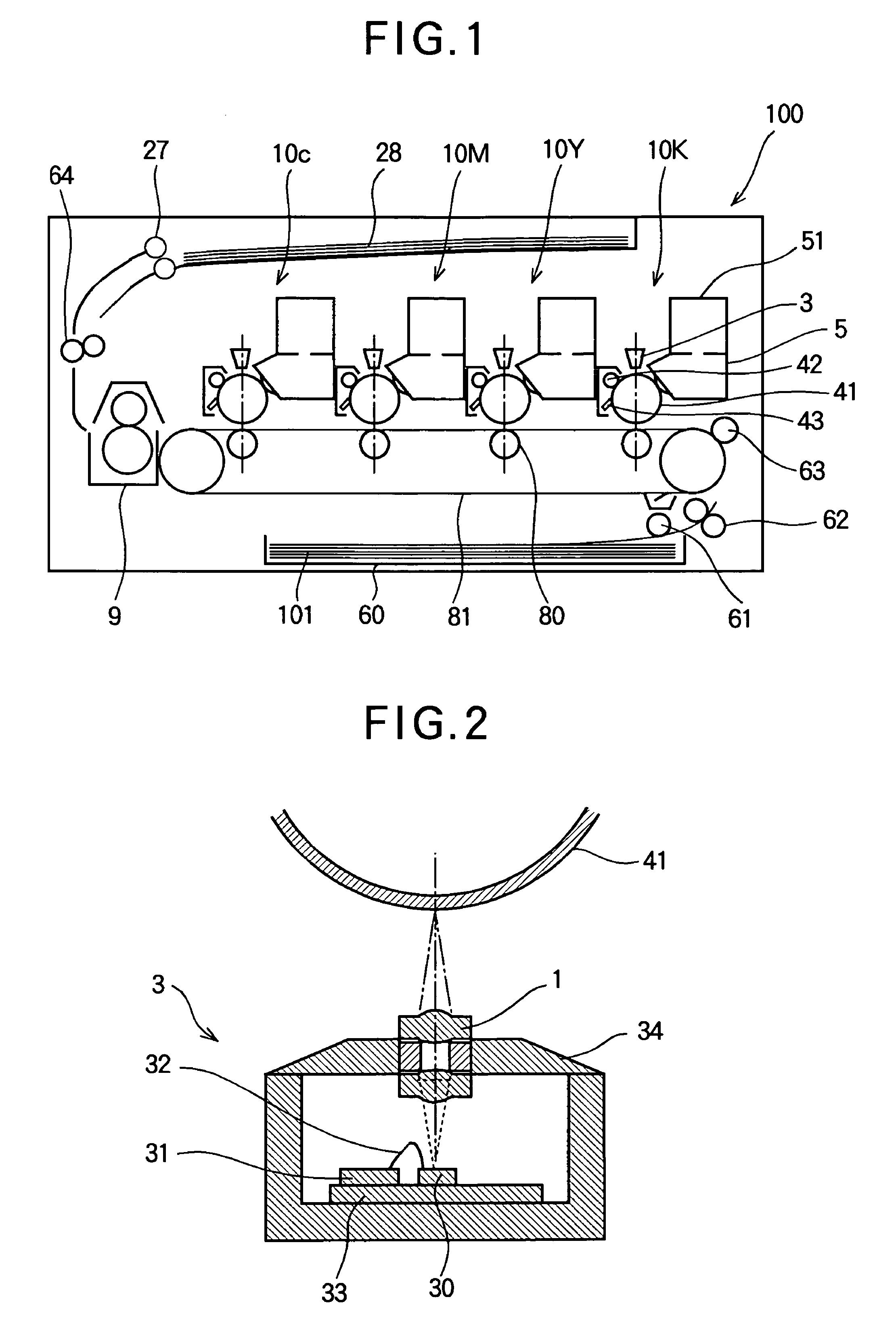
[0034]FIG. 1 is a side view schematically showing an electrophotographic printer as an image forming apparatus according to Embodiment 1 of the present invention. First, description will be made of a configuration of the electrophotographic printer.
[0035]In FIG. 1, the electrophotographic printer 100 (hereinafter, simply referred to as a printer) is configured to form an image on a printing medium based on image data using a toner containing pigment as a coloring agent. The printer 100 includes a sheet cassette 60 in which sheets 101 (as printing media) are stored, a feeding roller 101 that feeds the sheet 101 out of the sheet cassette 60 and carrying rollers 62 and 63 that carry the sheet 101 along a sheet feeding path.
[0036]The printer 100 of Embodiment 1 is a color electrophotographic printer, and includes image forming portions 10K, 10Y, 10M and 10C for forming images of black, yellow, magenta and cyan. The image forming portions 10K, 10Y, 10M and 10C have the same configuration...
embodiment 2
[0101]Next, Embodiment 2 of the present invention will be described. In Embodiment 2, the light absorbing portion is formed on a part of the inner surface of each opening 13a. FIG. 17 is an exploded perspective view showing the light shielding member 13 of the lens array according to Embodiment 2. In FIG. 17, the light shielding member 13 is divided at a plane parallel to axes of the cylindrical portions of the openings 13a. Shapes and positions of the light shielding portions 13c formed on parts of the inner surfaces of the openings 13a are shown in FIG. 17. The light absorbing portions 13c have substantially band shapes which are substantially parallel to the cylindrical portions of the openings 13a, i.e., substantially parallel to the optical axes of the microlenses 12.
[0102]FIG. 18 is a plan view showing the opening 13a formed on the light shielding portion 13 according to Embodiment 2. The arranging direction of the openings 13a is the above-below direction in FIG. 18. The open...
embodiment 3
[0117]Next, Embodiment 3 of the present invention will be described. Embodiment 3 relates to a reading apparatus employing the lens array according to Embodiment 1 or 2. FIG. 21 is a schematic view showing a configuration of the reading apparatus employing the lens array according to Embodiment 1 or 2.
[0118]In FIG. 21, a numeral 500 indicates a scanner as a reading apparatus that generates electric data of a manuscript. The scanner 500 includes a reading head 400, a manuscript table 502, rails 503, pulleys 504, a driving belt 505 and a motor 506. The reading head 400 takes in the lights reflected by the surface of the manuscript 507, and converts the images into the electric data. The reading head 400 is movably provided on the rail 503. The manuscript 507 is placed on the manuscript table 502. The manuscript table 502 is formed of a material that transmits a visible light. The reading head 400 is provided with a lamp 501 as an illumination unit. The light emitted by the lamp 501 is...
PUM
 Abstract
Description
Claims
Application Information
 - R&D
- Intellectual Property
- Life Sciences
- Materials
- Tech Scout
- Unparalleled Data Quality
- Higher Quality Content
- 60% Fewer Hallucinations
Browse by: Latest US Patents, China's latest patents, Technical Efficacy Thesaurus, Application Domain, Technology Topic, Popular Technical Reports.
© 2025 PatSnap. All rights reserved.Legal|Privacy policy|Modern Slavery Act Transparency Statement|Sitemap|About US| Contact US: help@patsnap.com