
Energy storage unit for a radar level gauge system

a technology of energy storage unit and radar level gauge, which is applied in the direction of reradiation, using reradiation, radio wave reradiation/reflection, etc., can solve the problems of limited available power, difficult to achieve power provision in practice, and increase the demand for power, etc., to achieve the effect of improving energy storag

Active Publication Date: 2011-05-31
ROSEMOUNT TANK RADAR
View PDF14 Cites 27 Cited by
  • Summary
  • Abstract
  • Description
  • Claims
  • Application Information

AI Technical Summary

Benefits of technology

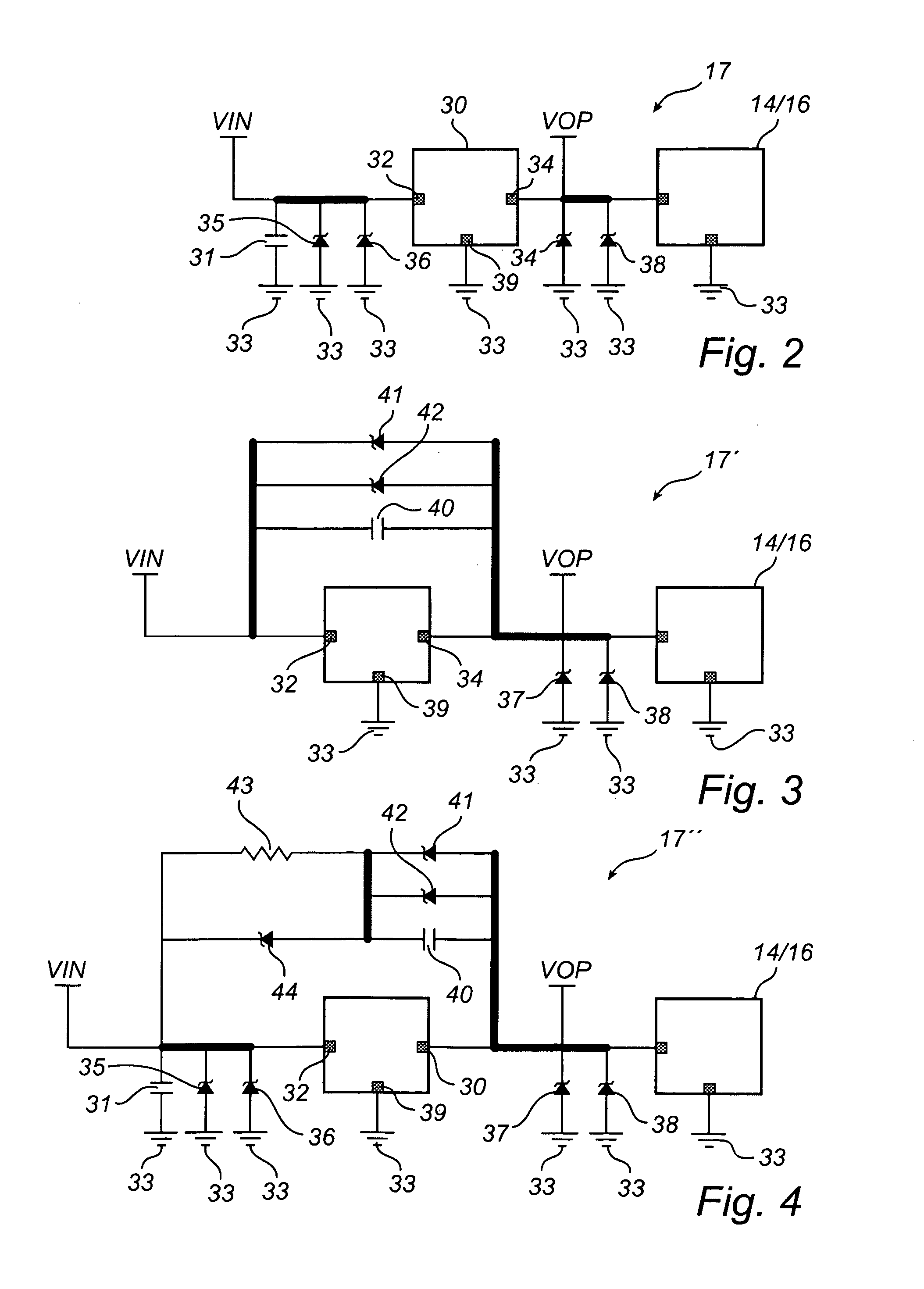
The present invention provides a radar level gauge system with improved energy storage without violating safety regulations. The system includes a microwave unit, a power supply circuit, and a power management circuitry. The power management circuitry includes a DC-DC converter and an energy storage capacitor connected between the input and output terminals of the converter. The energy storage capacitor allows for a sufficient amount of energy storage without exceeding the safety regulations. The system can be used in a two-wire interface or a four-wire interface for transmitting measurement data and receiving power for operation. The system can also include a current control unit to regulate the current in the interface. The invention also provides a method for regulating the operating power to the radar level gauge system using microwaves for measuring a level of a surface of a product in a container. The technical effects of the invention include improved energy storage without violating safety regulations, improved pulsed measuring, and improved FMCW measuring.

Problems solved by technology

In combination, this results in an increased demand of power during certain parts of the measuring cycle.
However, the provision of power is relatively difficult to achieve in practice, since energy is normally a scarce resource in the above-discussed type of gauges.
In particular, limited available power is a problem in systems using a two wire feeding system.
In case of a 4-20 mA loop, the available power is thus dependent upon the signal value of the gauge, so that during periods with low signal value (e.g. around 4 mA) only a very limited power is available.
Even during periods of high signal value (e.g. around 20 mA) the available power may not be sufficient to power the processing circuitry and the microwave emitter during a measurement cycle.
In the case where measurements are made in a tank containing explosive gas or liquids or in any other situation where the sensor is located in an explosion endangered area, there is also an issue of explosion protection.
However, these IS requirements also limit the levels of energy storage allowed in the installation at given voltage and current levels.
Such limitations apply to any energy store present in the system, such as capacitance and inductance, and severely limits the applicability of energy storage solutions as outlined above.
In many cases this results in a need for the cumbersome and expensive process of encasing the circuitry, e.g. by molding, and in other cases even encasement is not accepted by the safety regulations as a means to ensure an explosion proof installation.

Method used


Image

  • Energy storage unit for a radar level gauge system
  • Energy storage unit for a radar level gauge system
  • Energy storage unit for a radar level gauge system

Examples


Embodiment Construction

[0029]The present invention will now be described more fully hereinafter with reference to the accompanying drawings, in which currently preferred embodiments of the invention are shown. This invention may, however, be embodied in many different forms and should not be construed as limited to the embodiments set forth herein; rather, these embodiments are provided for thoroughness and completeness, and fully convey the scope of the invention to the person skilled in the art. Like reference characters refer to like elements throughout.

[0030]FIG. 1 shows a schematic block diagram of a radar level gauge system 10, in which the present invention advantageously can be implemented. The radar level gauge system is arranged to determine the position of the surface of a material 11 in a tank 12 (i.e. the level of the material 11). The radar level gauge system 10 includes a microwave unit 13, adapted to emit waves into the tank, and to receive reflected microwaves, processing circuitry 16 for...


PUM


Abstract

A radar level gauge system comprising power management circuitry for regulating operating power to be used by a microwave unit and a processing circuitry of the radar level gauge system. The power management circuitry comprises a DC-DC converter having an input terminal connected to the interface, an output terminal connected to the microwave unit and the processing circuitry, and a reference terminal connected to an electrical reference point, wherein a first voltage level at the input terminal and a second voltage level at the output terminal relates to a reference voltage level at the electrical reference point. The power management circuitry further comprises an energy storage capacitor connected between the input and output terminals of the DC-DC converter. According to this design, the capacitance of the power management circuitry gets reduced due to that the capacitance is originating from a series capacitance.

Description

TECHNICAL FIELD OF THE INVENTION[0001]The present invention relates to a radar level gauge system using microwaves for measuring a level of a surface of a product in a container. More specifically, the invention relates to energy storage in such a gauge.TECHNICAL BACKGROUND[0002]Radar level gauges are suitably used for making non-contact measurements of the level of products such as process fluids, granular compounds and other materials. An example of such a radar level gauge system can include a microwave unit for transmitting microwaves towards the surface and receiving microwaves reflected by the surface, processing circuitry arranged to communicate with said microwave unit and to determine said level based on a relation between transmitted and received microwaves, an interface for connecting said processing circuitry externally of said radar level gauge, and a power management circuitry providing said microwave unit and said processing circuitry with operating power.[0003]In ord...

Claims


Application Information

Patent Timeline
Patent Type & Authority Patents(United States)
IPC IPC(8): G01S13/08G01S7/28
CPCG01S7/02G01S13/88G01S7/35G01S7/282
Inventor NILSSON, LEIF
Owner ROSEMOUNT TANK RADAR
Learn More