
Permanent-magnet type electric rotating machine and permanent-magnet type electric rotating machine system for automobile or train

a technology of permanent magnet and rotating machine, which is applied in the direction of magnetic circuit rotating parts, magnetic circuit shape/form/construction, electric devices, etc., can solve the problems of stress and demagnetization, and achieve the effect of preventing heat demagnetization

Inactive Publication Date: 2011-05-31
HITACHI LTD
View PDF7 Cites 16 Cited by
  • Summary
  • Abstract
  • Description
  • Claims
  • Application Information

AI Technical Summary

Benefits of technology

[0004]In the case of the railroad-vehicle-targeted motor, its weight exerts a significant influence on the riding comfort feeling of the railroad vehicle. Accordingly, a weight reduction in the electric rotating machine becomes important. The light-weighted implementation of the electric rotating machine increases its output density. Nevertheless, the small-sized implementation in the constitution of the electric rotating machine increases an influence exerted by the magnetic saturation inside the rotating machine. As a result, a current passing through to the stator is increased in order to satisfy the specification output. The increase in the current also increases a magnet eddy current caused by the armature reaction. Moreover, the increase in the magnet eddy current causes the magnet to liberate heat, thereby giving rise to a problem of the demagnetization. This problem requires the execution of a demagnetization countermeasure against the heat liberation due to the magnet eddy current.
[0007]According to the present invention, it becomes possible to prevent the heat demagnetization due to the eddy current, which is induced in a manner of being concentrated onto the edge portions of the permanent magnet on the outer-diameter side of the rotor iron-core.

Problems solved by technology

Moreover, the increase in the magnet eddy current causes the magnet to liberate heat, thereby giving rise to a problem of the demagnetization.
This problem requires the execution of a demagnetization countermeasure against the heat liberation due to the magnet eddy current.
This acute angle gives rise to a problem of a stress due to the centrifugal force.

Method used


Image

  • Permanent-magnet type electric rotating machine and permanent-magnet type electric rotating machine system for automobile or train
  • Permanent-magnet type electric rotating machine and permanent-magnet type electric rotating machine system for automobile or train
  • Permanent-magnet type electric rotating machine and permanent-magnet type electric rotating machine system for automobile or train

Examples


1st embodiment

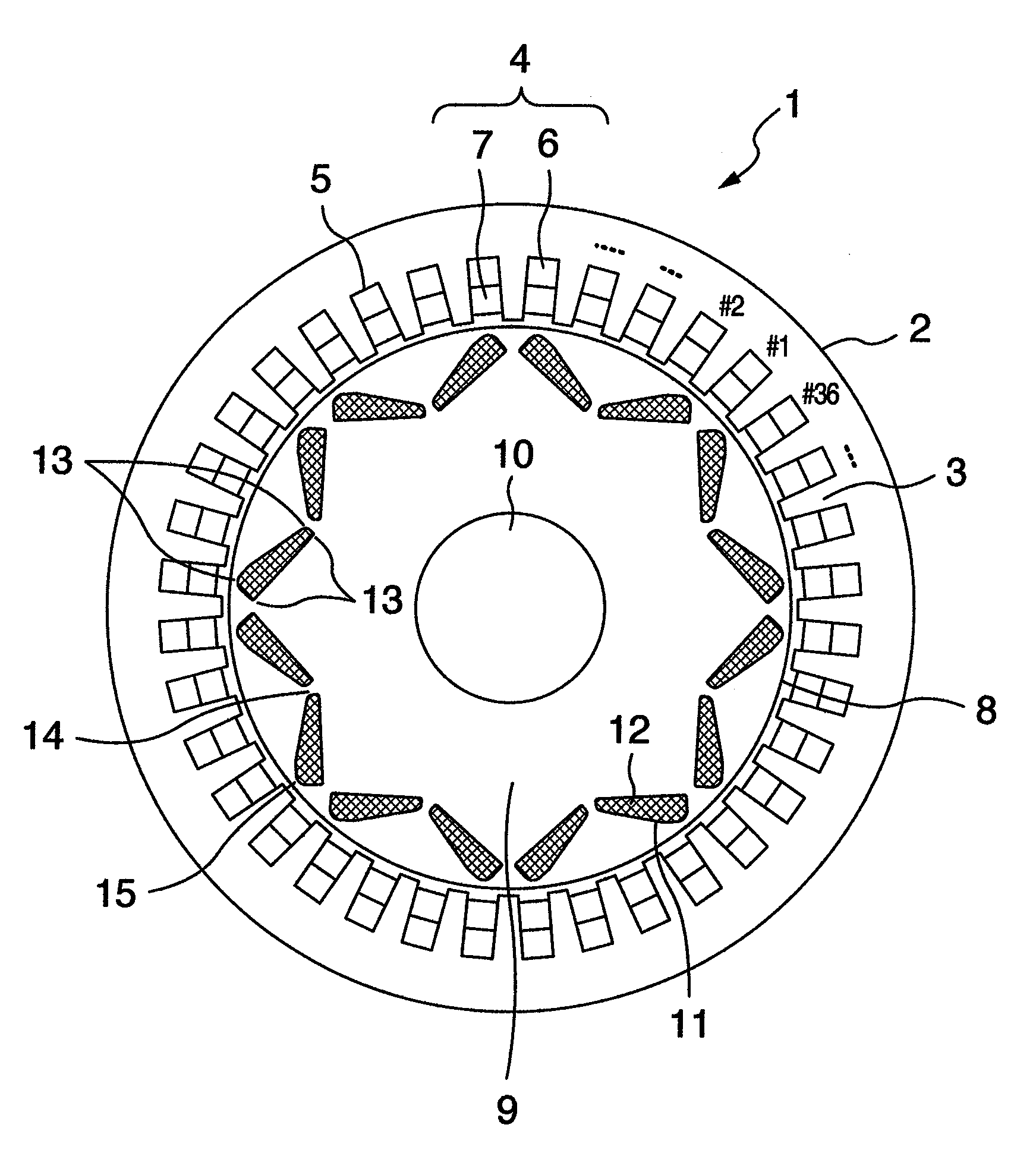
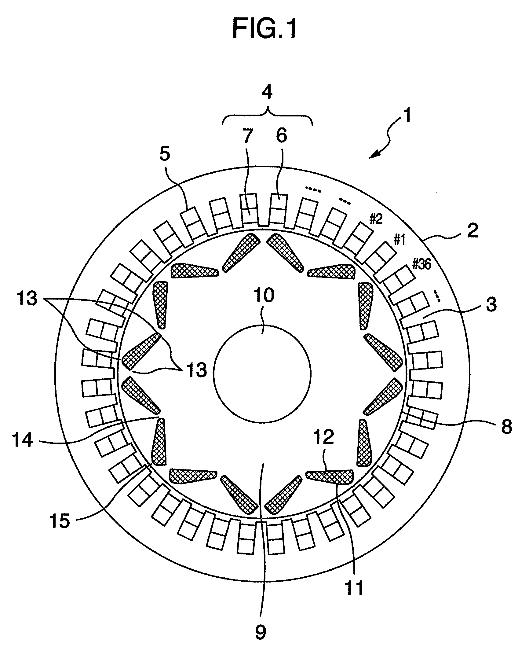
[0020]FIG. 1 is a cross-sectional diagram of the permanent-magnet type electric rotating machine, which becomes a first embodiment of the present invention. The permanent-magnet type electric rotating machine 1 is an 8-pole & 36-slot electric rotating machine. This 8-pole & 36-slot machine is used for a a-few-hundreds-of-kW-class train, and rotates in a range of 300 to 7000 min−1. A stator 2 is a distribution-winding stator, which includes a cylindrical stator iron-core equipped with a plurality of teeth 3 that protrude from a yoke portion onto its inner-circumference surface, and which also includes a coil 4 formed by winding an elemental wire in a distribution-like manner using the teeth 3. The coil 4 is configured by winding a 3-phase (i.e., U-phase, V-phase, and W-phase) winding so that the 8 poles are electrically implemented with the 36 slots. An upper coil 6 is deployed on the outer-diameter side of each slot 5 formed between the teeth 3, and a lower coil 7 is deployed on the...

2nd embodiment

[0025]FIG. 4 is a one-half edge-portion cross-sectional diagram of the rotor, which becomes a second embodiment of the present invention. A concave portion 16 is allowed to be provided in the outer circumference portion of the rotor iron-core 9, which becomes the center of the V-character pattern of the rotor 8, and which has been illustrated in the first embodiment. Providing the concave portion 16 makes it possible to reduce the weight of the iron-core which becomes the central portion of the V-character pattern, thereby allowing a reduction in the concentration stress concentrated onto the connection portion 14 which becomes the inner-diameter side of the rotor iron-core 9 of the V-character pattern's center. Moreover, an air layer is created in the portion in which the concave portion 16 has been provided. This air layer allows implementation of a reduction in the temperature transmitted to the permanent magnet 12. Also, a similar effect can be obtained by providing an empty hol...

3rd embodiment

[0026]FIG. 5 is a one-half edge-portion cross-sectional diagram of the rotor, which becomes a third embodiment of the present invention. The concave portion 16 is allowed to be provided in the inter-pole outer circumference in which polarities of the rotor 8 differ from each other, and which has been illustrated in the first and second embodiments. Providing the concave portion 16 creates an air layer. This air layer allows implementation of a reduction in the temperature transmitted to the permanent magnet 12.


PUM


Abstract

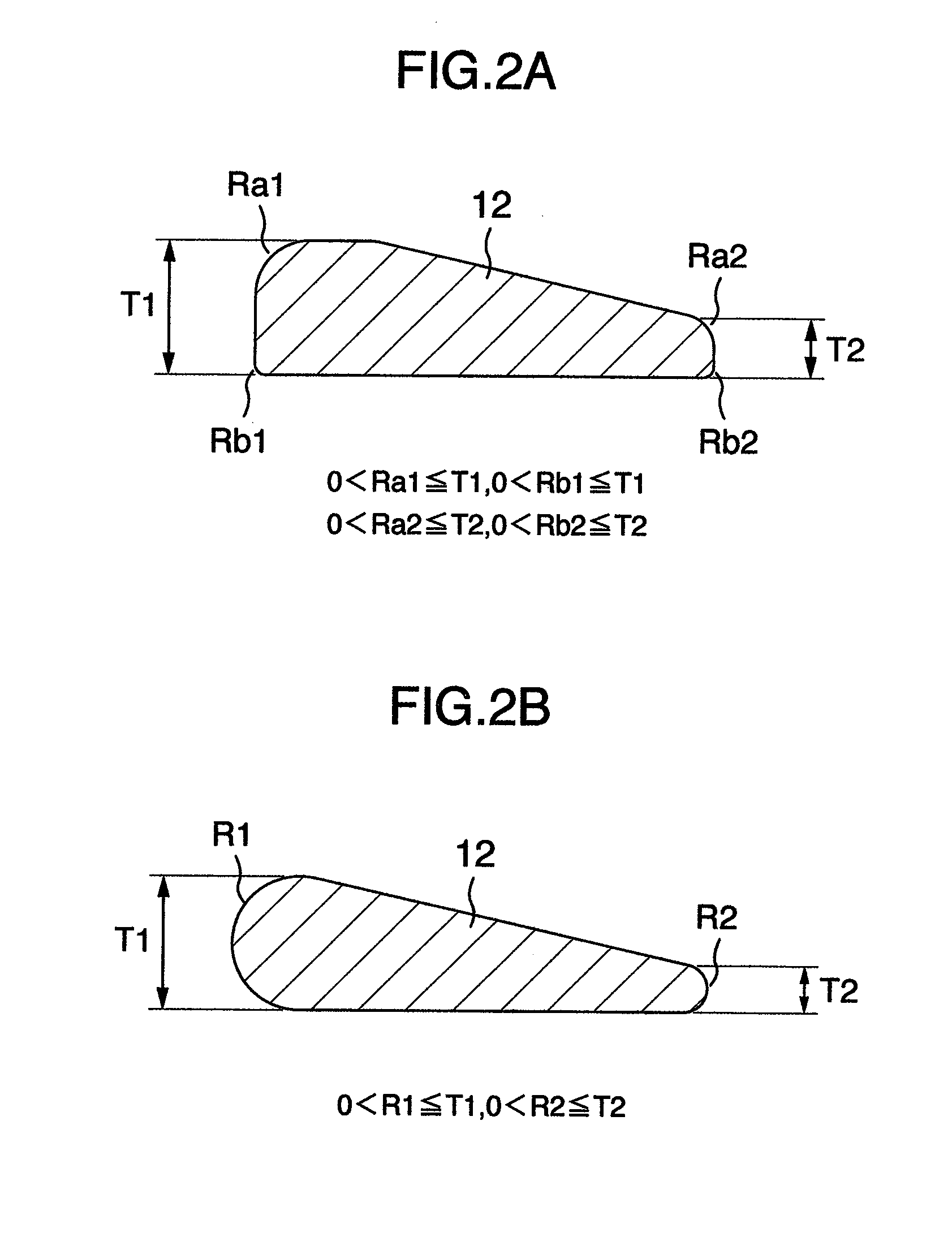
A rotor is deployed such that the rotor becomes coaxially rotatable with a stator. A shaft is fixed onto the axis of a rotor iron-core. 1-pole constituting magnet slots are deployed into V-character pattern along an outer circumference portion of the rotor iron-core. Permanent magnets are embedded into the magnet slots. For the 1 pole, the 2 pieces of same-polarity permanent magnets are embedded into the V-character pattern. The configuration of each embedded permanent magnet is designed as follows: From the thickness of the permanent-magnet edge portion on the inner-diameter side of the rotor iron-core, which becomes the center of the V-character pattern, the thickness of the permanent magnet gradually increases toward the outer-diameter side of the rotor iron-core, which become the right and left edge portions of the V-character pattern. Simultaneously, curved lines are provided on both edge portions of the permanent magnet.

Description

BACKGROUND OF THE INVENTION[0001]The present invention relates to a permanent-magnet type electric rotating machine, and an automobile-or-train-targeted permanent-magnet type electric rotating machine system including the same machine.[0002]Up to the present time, an induction motor has been employed as the electric rotating machine used for railroad vehicles. In recent years, however, there has been a growing trend to employ a permanent-magnet type electric rotating machine which allows its small-sized and light-weighted implementation and high-efficiency implementation. This growing trend has arisen from low-cost implementation of the permanent magnet and prevalence of the high-performance inverter.[0003]Under the circumstances like this, in order to improve electric characteristics and strength characteristics of the electric rotating machine, consideration is now being given to the permanent-magnet type rotor structure of various forms. In JP-A-9-90517, the following permanent-m...

Claims


Application Information

Patent Timeline
Patent Type & Authority Patents(United States)
IPC IPC(8): H02K1/27
CPCH02K1/2766B60L3/0061B60L11/1803Y02T10/641B60L2240/36B60L2260/28Y02T10/7005B60L2200/26B60L50/51Y02T10/64Y02T10/70
Inventor KORI, DAISUKEKIMURA, MAMORUMIKAMI, HIROYUKIMASUDA, SEIKICHIFUJIEDA, MASAYASU
Owner HITACHI LTD
Learn More