
Multifocal light concentrator for a device for the conversion of radiation, and in particular for the conversion of solar radiation into electrical, thermal or chemical energy

a multi-focal light and concentrator technology, applied in the field of light concentrators, can solve the problems of compromising the conversion efficiency of the cell and the integrity of the lens itself, and the economic and technical aspects of solar energy use, and achieve the effect of high efficiency values

Inactive Publication Date: 2011-05-31
CENT RICERCHE FIAT SCPA
View PDF22 Cites 5 Cited by
  • Summary
  • Abstract
  • Description
  • Claims
  • Application Information

AI Technical Summary

Benefits of technology

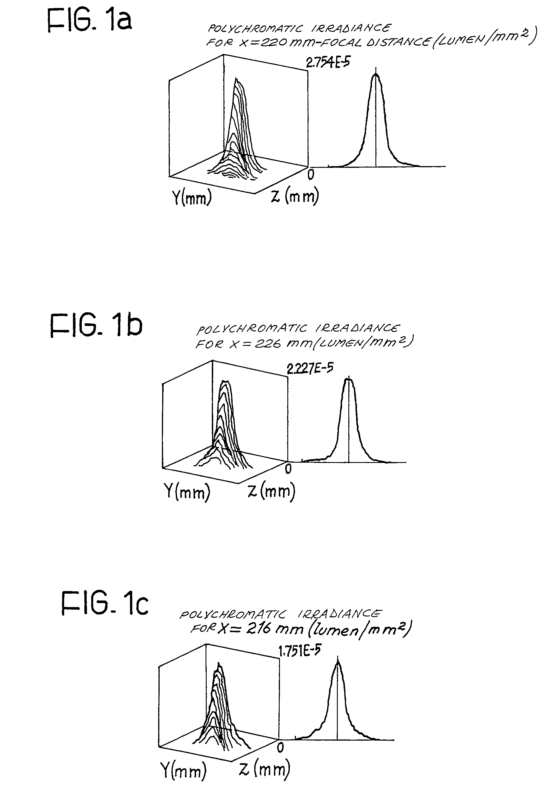
[0014]The aim of the present invention is to produce a concentrator in transmission having high efficiency values (above 80%) and at the same time uniformity in the distribution of polychromatic irradiance on the plane of the cell.
[0015]This aim is achieved according to the invention by a light concentrator for a radiation conversion device having the characteristics defined in Claim 1. This aim is therefore achieved by means of a Fresnel lens that is multifocal, or having a focal length which is not constant but variable in dependence on the distance from the centre of the lens itself, the variation of said focal length being determined so as to maximise the distribution of polychromatic irradiance on the plane of the cell.

Problems solved by technology

As is known, the use of solar energy presents technical and economic problems linked to the low energetic density of solar radiation, to its discontinuity (alternation of day / night, cycle of seasons, variation in the meteorological conditions) and to the modest value of the conversion yields (typically below 25%).
The presence of irradiance peaks on the plane of the cell is generally a problem, inasmuch as it means that the regions of the cell with higher irradiance reach very high temperatures, compromising both the conversion efficiency of the cell and the integrity of the lens itself.

Method used


Image

  • Multifocal light concentrator for a device for the conversion of radiation, and in particular for the conversion of solar radiation into electrical, thermal or chemical energy
  • Multifocal light concentrator for a device for the conversion of radiation, and in particular for the conversion of solar radiation into electrical, thermal or chemical energy
  • Multifocal light concentrator for a device for the conversion of radiation, and in particular for the conversion of solar radiation into electrical, thermal or chemical energy

Examples


Embodiment Construction

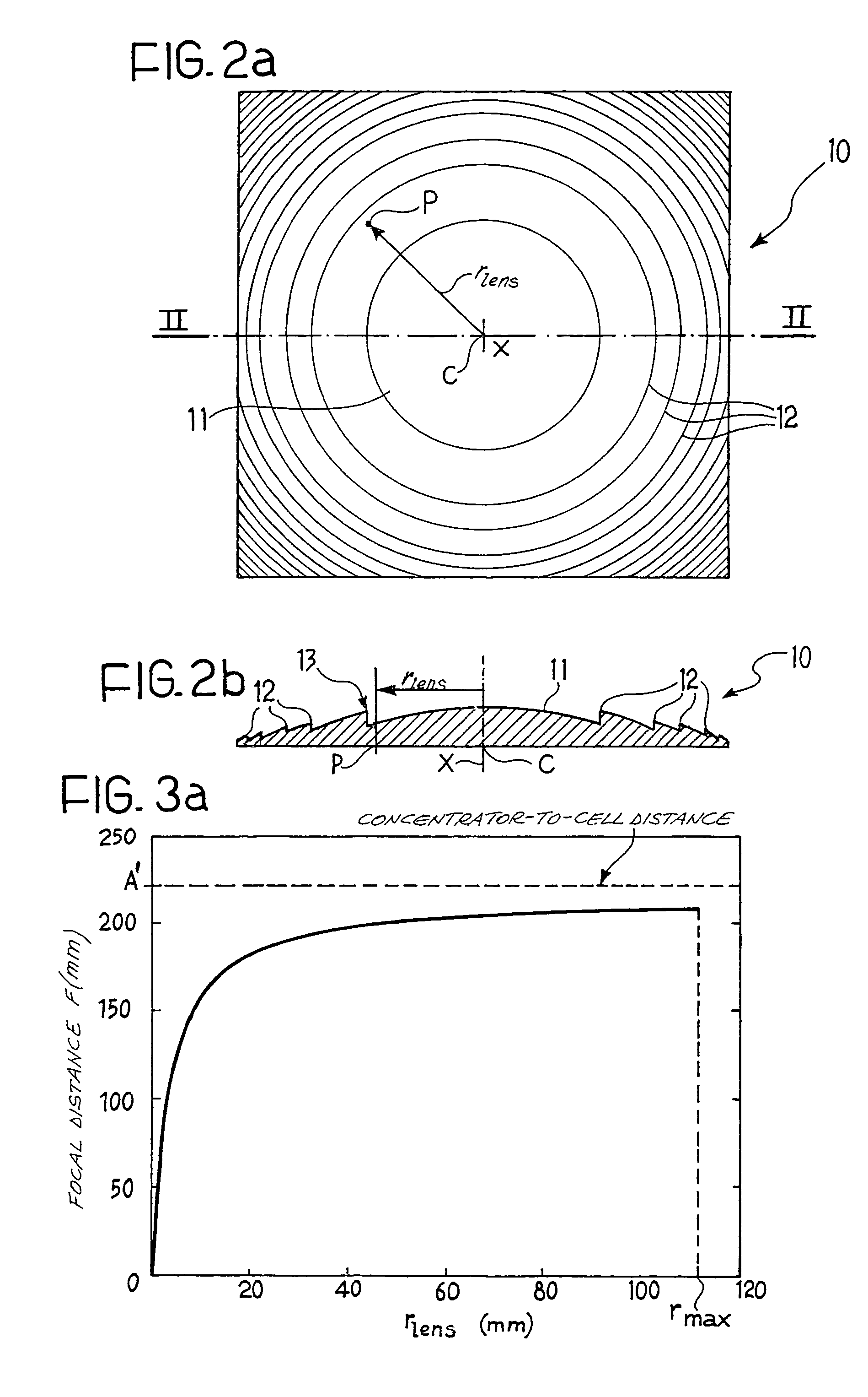
[0033]With reference to FIGS. 2a, b, a concentrator 10 according to the invention is illustrated, capable of concentrating the luminous (and, if required, infrared and ultraviolet) radiation incident on a conversion device (not illustrated) capable of converting such radiation into another form of energy, for example electrical, thermal or chemical energy. Hereinafter, for such a device, for the sake of simplicity reference will be made to a conventional photovoltaic cell.

[0034]The concentrator 10, having a square shape in the present example, is formed substantially of a multifocal Fresnel lens. The term “multifocal” means that, given a general point P of the lens placed at a distance rlens from the centre C of the lens itself, the focal distance F is dependent on rlens; the focal distance F(rlens) at the point P is defined as the distance between the plane of the lens and the plane perpendicular to the optical axis x and passing through the point of intersection between the optica...


PUM


Abstract

A light concentrator is described, for a device for the conversion of solar radiation into electrical, thermal or chemical energy, capable of conveying the radiation towards a surface of the conversion device. The concentrator comprises at least one portion of Fresnel lens of rotational symmetry, one face of which has a plurality of crests disposed concentrically about a center so as to form a segmented transverse profile of the portion of Fresnel lens. The profile is formed in such a manner that the focal distance of the Fresnel lens is variable in dependence on the radial distance from the center of the lens. The variation of the focal distance is determined such that, when the Fresnel lens is illuminated by polychromatic radiation, the superposition of the distributions of irradiance, produced by the lens at the individual wavelengths constituting the spectrum of the incident radiation, generates a substantially uniform distribution of polychromatic irradiance on the conversion device.

Description

BACKGROUND OF THE INVENTION[0001]The present invention refers to a light concentrator, of the type used in particular in devices for the conversion of the radiant energy of the luminous radiation emitted by the sun into chemical, thermal or electrical energy, such as for example photovoltaic cells.[0002]As is known, the use of solar energy presents technical and economic problems linked to the low energetic density of solar radiation, to its discontinuity (alternation of day / night, cycle of seasons, variation in the meteorological conditions) and to the modest value of the conversion yields (typically below 25%).[0003]Such factors render the difference between the potential capacities and the practical possibilities of use significant. Among the various technologies perfected up to now for the exploitation of solar energy, photovoltaic technology is the most promising, in the medium or long term, by virtue of its characteristics of modularity, simplicity, reliability and reduced req...

Claims


Application Information

Patent Timeline
Patent Type & Authority Patents(United States)
IPC IPC(8): H01L31/00F24J2/38F24J2/40G02B3/08H01L25/00H01L31/042G02B13/00F24S23/30F24S50/20G02B3/00H01L31/052
CPCF24J2/085G02B3/08H01L31/0232Y02E10/52H01L31/04Y02E10/43F24S23/31H01L31/0543Y02E10/40
Inventor REPETTO, PIERMARIOBOLLEA, DENISCAPELLO, DAVIDEBERNARD, STEFANOPERLO, PIETRO
Owner CENT RICERCHE FIAT SCPA
Learn More