Composite triangular-pyramidal cube-corner retroreflective sheeting and retroreflective articles
a triangular-pyramidal cube and corner retroreflective technology, applied in the field of composite triangular-pyramidal cubecorner retroreflective sheeting of novel structure and retroreflective articles, can solve the problems of inconvenient practical application of retroreflective light with excessively narrow divergence angle, and the defect of inferior retroreflectivity of retroreflective sheeting and retroreflective articles using triangular-pyramidal cub
- Summary
- Abstract
- Description
- Claims
- Application Information
AI Technical Summary
Benefits of technology
Problems solved by technology
Method used
Image
Examples
example 1
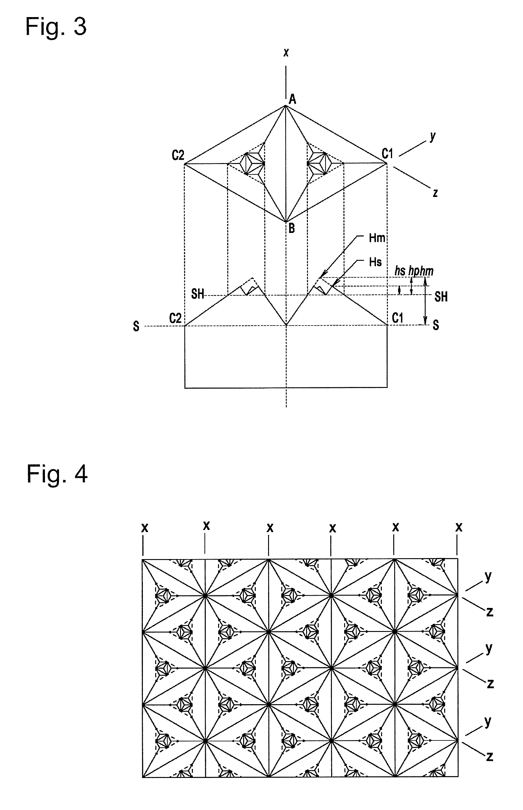
[0101]A composite retroreflective element of the configuration as illustrated in FIG. 3 wherein, on a main reflective element having an optical axis with an angle of tilt of +7° and a distance (hm) from the imaginary apex (Hm) at which the three reflective lateral faces forming the main reflective element would cross with each other, to the main plane (S-S) of 130 μm, a group of four sub-reflective elements were arrayed, each having an optical axis with an angle of tilt of +7° and a height (hs) of 30 μm, was prepared by the same method as used in Comparative Example 1.
[0102]The ratio (hs / hm) of the distance (hs) from the apex (Hs) of the sub-reflective element to the sub-plane (SH-SH) to the distance (hm) from the imaginary apex (Hm) of the main reflective element to the main plane (S-S) in the composite reflective element was 0.23, the distance (hp) from the imaginary apex (Hm) of the main reflective element to the sub-reflective plane (SH-SH) was 50 μm, and the ratio (hp / hm) was 0...
example 2
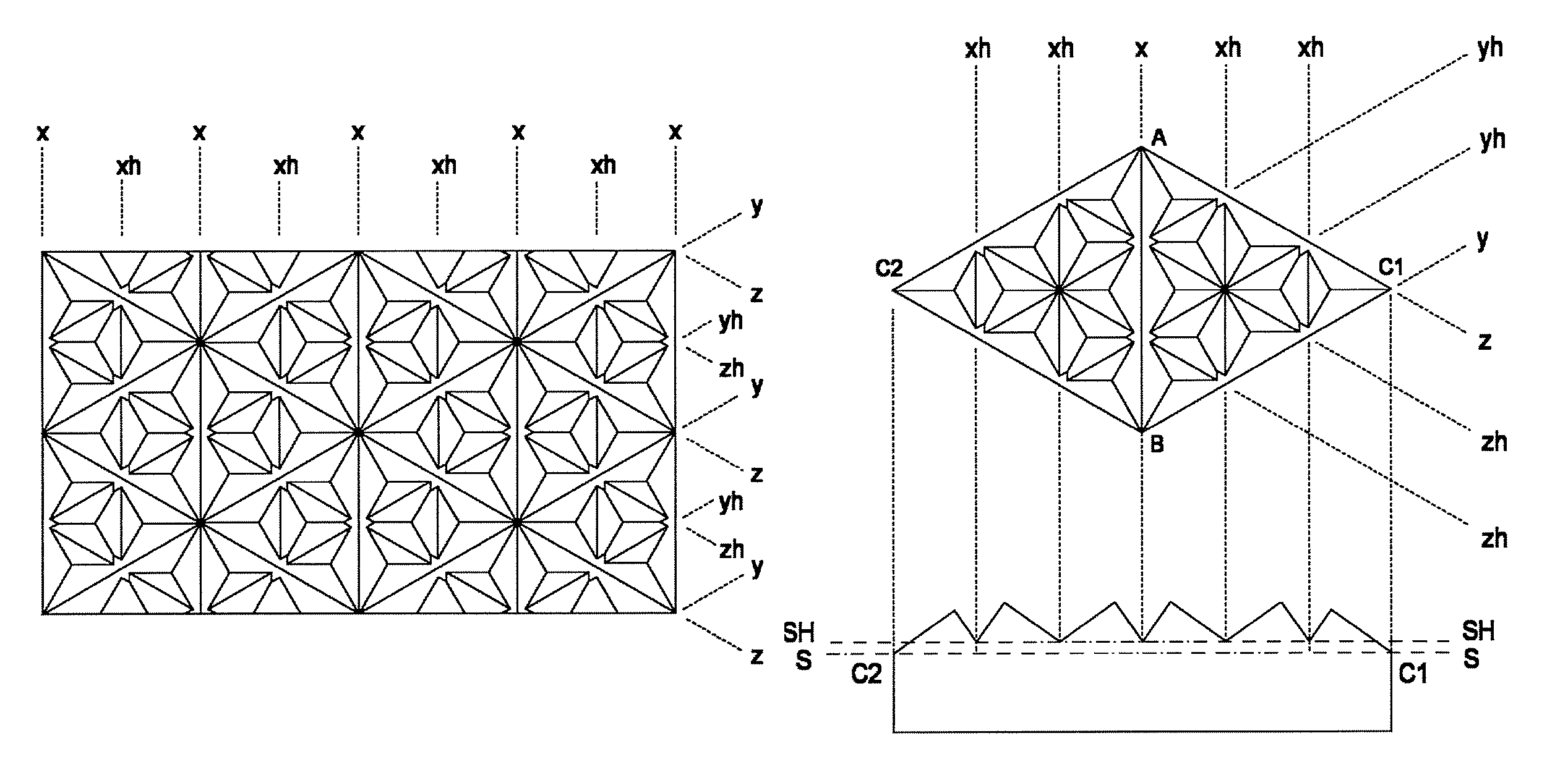
[0104]A composite retroreflective element of the configuration as illustrated in FIG. 6 wherein, on a main reflective element having an optical axis with an angle of tilt of +7° and a distance (hm) from the imaginary apex (Hm) at which the three reflective lateral faces forming the main reflective element would cross with each other, to the main plane (S-S) of 130 μm, a group of sixteen sub-reflective elements were arrayed, each having an optical axis with an angle of tilt of +7° and a height (hs) of 30 μm, was prepared by the same method as used in Comparative Example 1.
[0105]The ratio (hs / hm) of the distance (hs) from the apex (Hs) of the sub-reflective element to the sub-plane (SH-SH) to the distance (hm) from the imaginary apex (Hm) of the main reflective element to the main plane (S-S) in the composite reflective element was 0.23, the distance (hp) from the imaginary apex (Hm) of the main reflective element to the sub-reflective plane (SH-SH) was 65 μm, and the ratio (hp / hm) wa...
example 3
[0107]A composite retroreflective element of the configuration as illustrated in FIG. 9 wherein, on a main reflective element having an optical axis with an angle of tilt of −6° and a distance (hm) from the imaginary apex (Hm) at which the three reflective lateral faces forming the main reflective element would cross with each other, to the main plane (S-S) of 180 μm, a group of four sub-reflective elements were arrayed, each having an optical axis with an angle of tilt of −6° and a height (hs) of 70 μm, was prepared by the same method as used in Comparative Example 1. Because the four sub-reflective elements had slightly different heights, the distance between the apex of the central, highest sub-reflective element and the sub-plane (SH-SH) was chosen as the height hs.
[0108]The ratio (hs / hm) of the distance (hs) from the apex (Hs) of the sub-reflective element to the sub-plane (SH-SH) to the distance (hm) from the imaginary apex (Hm) of the main reflective element to the main plane...
PUM
 Abstract
Description
Claims
Application Information
 - R&D
- Intellectual Property
- Life Sciences
- Materials
- Tech Scout
- Unparalleled Data Quality
- Higher Quality Content
- 60% Fewer Hallucinations
Browse by: Latest US Patents, China's latest patents, Technical Efficacy Thesaurus, Application Domain, Technology Topic, Popular Technical Reports.
© 2025 PatSnap. All rights reserved.Legal|Privacy policy|Modern Slavery Act Transparency Statement|Sitemap|About US| Contact US: help@patsnap.com


