
Layout circuit having a combined tie cell

a technology of layout circuit and tie cell, which is applied in the direction of cad circuit design, pulse technique, instruments, etc., can solve problems such as congestion of routing

Active Publication Date: 2011-05-24
MEDIATEK INC
View PDF15 Cites 11 Cited by
  • Summary
  • Abstract
  • Description
  • Claims
  • Application Information

AI Technical Summary

Benefits of technology

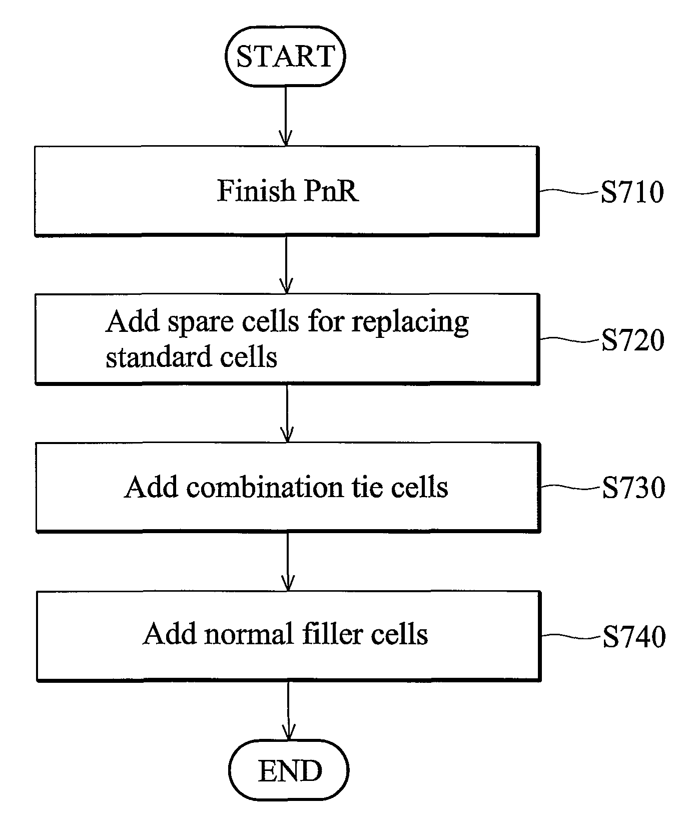
The patent text describes a method for designing a layout circuit for an integrated circuit. The method includes placing and routing standard cells on a layout area, adding a spare cell for replacing a standard cell, and adding a combined tie cell for tying a voltage to the replaced standard cell. The technical effect of this method is to improve the flexibility and efficiency of designing integrated circuits.

Problems solved by technology

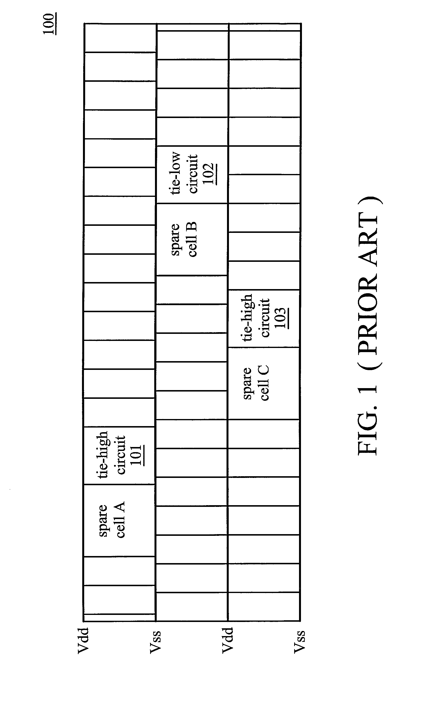
However, these spare cells initially do not connect to any standard cells, and thus these spare cells should connect to tie-high cells or tie-low cells in order to avoid floating.
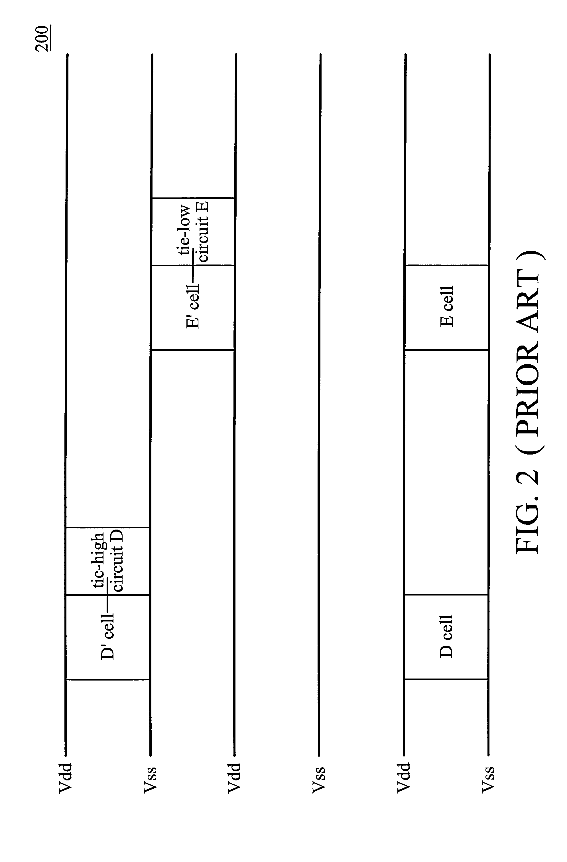
However, the replaced standard cell D and E may be distant from their corresponding tie cells, thus causing routing congestion.

Method used


Image

  • Layout circuit having a combined tie cell
  • Layout circuit having a combined tie cell
  • Layout circuit having a combined tie cell

Examples


Embodiment Construction

The following description is of the best-contemplated mode of carrying out the invention. This description is made for the purpose of illustrating the general principles of the invention and should not be taken in a limiting sense. The scope of the invention is best determined by reference to the appended claims.

FIG. 4 shows a schematic diagram of one part of layout area 400 of an integrated circuit according to an embodiment of the invention. Firstly, place and route standard cells and add spare cells on layout area 400. Some standard cells F, G, H, I and spare cells F′, G′, H′, I′, are shown on this part of layout area 400. Cells F, G, H and I are original standard cells for performing some specific functions of the first-tap-out chip. Spare cells F′, G′, H′ and I′ are added for possibly adding more functions or changing design circuits according to the engineering change order (ECO) after the first-tap-out. For example, spare cells F′, G′, H′ and I′ may replace original standard ...


PUM


Abstract

A layout circuit is provided, comprising standard cells, a spare cell, combined tie cells and normal filler cells. The standard cells are disposed and routed on a layout area. The spare cell is added on the layout area and provided for replacing one of the standard cells while adding or changing functions later. The combined tie cells are added on the layout area. The normal filler cells are added on the rest of the layout area. The combined tie cell comprises a tie-high circuit, a tie-low circuit and a capacitance circuit. Some standard cells are disposed near at least one combined tie cell for avoiding routing congestion between the combined tie cells and the replaced standard cell. A circuit layout method is also provided.

Description

BACKGROUND OF THE INVENTION1. Field of the InventionThe invention relates to circuit layout, and in particular relates to a circuit layout method and a layout circuit with combined tie cells.2. Description of the Related ArtAfter design engineers (hereinafter referred to as ‘engineers’) place and route standard cells on a layout area, engineers usually prepares some spare cells on the layout area for adding more functions or changing design circuits after the chip tap out. However, these spare cells initially do not connect to any standard cells, and thus these spare cells should connect to tie-high cells or tie-low cells in order to avoid floating.FIG. 1 shows a schematic diagram of one part of layout area 100 of an integrated circuit. There is no standard cell particularly shown on this part of layout area 100. Spare cells A and C are connected to tie-high cells 101 and 103 and spare cell B is connected to a tie-low cell 102. Thus, the voltages provided to spare cells A and C are ...

Claims


Application Information

Patent Timeline
Patent Type & Authority Patents(United States)
IPC IPC(8): G06F17/50H03K19/094H03K19/00G06F15/04H03K19/013
CPCG06F17/5068H01L27/11807H01L27/0207G06F2217/72G06F30/39G06F2117/06
Inventor TSAI, TUNG-KAILIN, CHIH-CHING
Owner MEDIATEK INC
Learn More