
Fuel cell system

a fuel cell and system technology, applied in the direction of fuel cells, reactant parameter control, electrical apparatus, etc., can solve the problem of inability to accurately follow the actual rotational frequency change, the possibility of secondary battery overcharge and overdischarge as a result, and the actual power generation level with respect to the target power generation value is excessively decreased, so as to reduce the likelihood of occurrence of an excessive increase, the effect of reducing the probability of an excessive decrease of the power generation level

Inactive Publication Date: 2011-05-24
TOYOTA JIDOSHA KK
View PDF7 Cites 2 Cited by
  • Summary
  • Abstract
  • Description
  • Claims
  • Application Information

AI Technical Summary

Benefits of technology

[0011]In a fuel cell system according to the present invention, the power generation calculation unit gradually changes the magnitude of the power generation level of the fuel cell at a time of transition between the first processing and the second processing, the power generation level at the time of transition being indicated in the output command input into the drive control unit for the oxidizing gas supply section. Accordingly, at a time of transition between the first processing and the second processing, a change in a target value of the drive state of the oxidizing gas supply section can be accurately followed by a change in the actual drive state. Therefore, it is possible to reduce the likelihood of occurrence of an excessive decrease of the power generation level with respect to a target value when the power generation level of the fuel cell is decreased, and to reduce the likelihood of occurrence of an excessive increase of the power generation level with respect to a target value when the power generation level of the fuel cell is increased. As a result, possibilities of occurrence of over-discharge and overcharge of the secondary battery can be reduced even when the secondary battery is discharged at a level close to an upper threshold of power discharge and when the secondary battery is charged at a level close to an upper threshold of power charge.

Problems solved by technology

In the fuel cell system described in JP 2004-281219 A, although it may be possible to warm up the fuel cell and the secondary battery quickly by alternately performing the first processing and the second processing, the possibility that overcharge and over-discharge may occur in the secondary battery as a result cannot be denied.
For example, while the drive state of an oxidizing gas supply section composed of an air compressor or the like must be controlled in order to cause the fuel cell to generate power, at the time of transition between the first processing and the second processing, there are possibilities that a change in a target value of the rotational frequency of the oxidizing gas supply section cannot be accurately followed by a change in the actual rotational frequency.
Accordingly, when the power generation level of the fuel cell is lowered, an undershoot may occur, resulting in an excessive decrease in the actual power generation level with respect to the target power generation value.
On the other hand, when the power generation level of the fuel cell is increased, an overshoot may occur, resulting in an excessive increase in the actual power generation level with respect to the target power generation value.
On the other hand, when an overshoot of the power generation level of the fuel cell occurs, during an increase in power charge of the secondary battery which is charged by receiving a supply of generated power, an overcharge exceeding an upper threshold of power charge tends to occur.
Such occurrences of over-discharge and overcharge of the secondary battery cause early deterioration of the secondary battery, and are therefore undesirable.
Under a low-temperature environment, performance of the secondary battery may be degraded not only at the time of system start-up but also during continuous power generation by the fuel cell.

Method used


Image

  • Fuel cell system
  • Fuel cell system
  • Fuel cell system

Examples


first embodiment

of the Invention

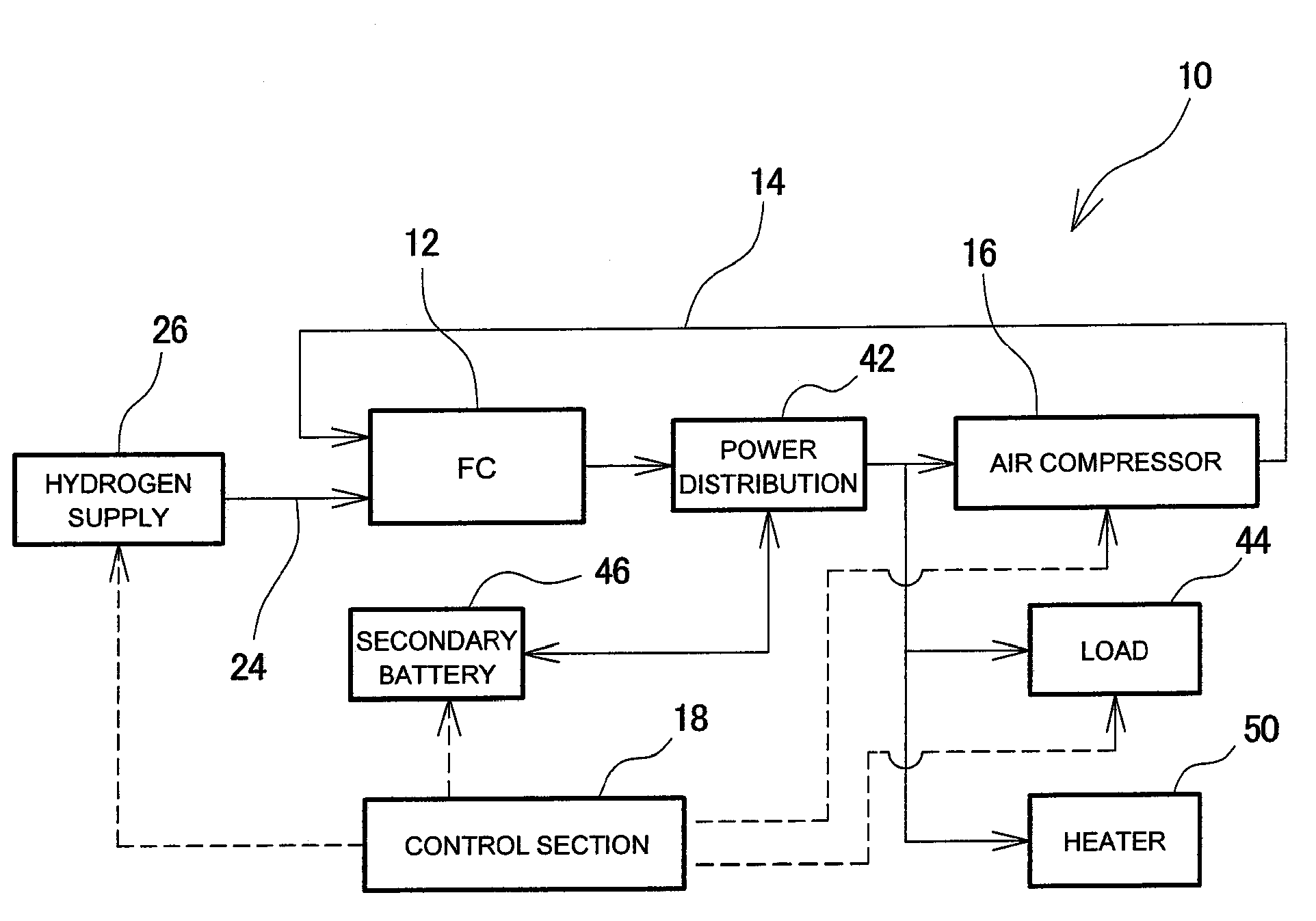
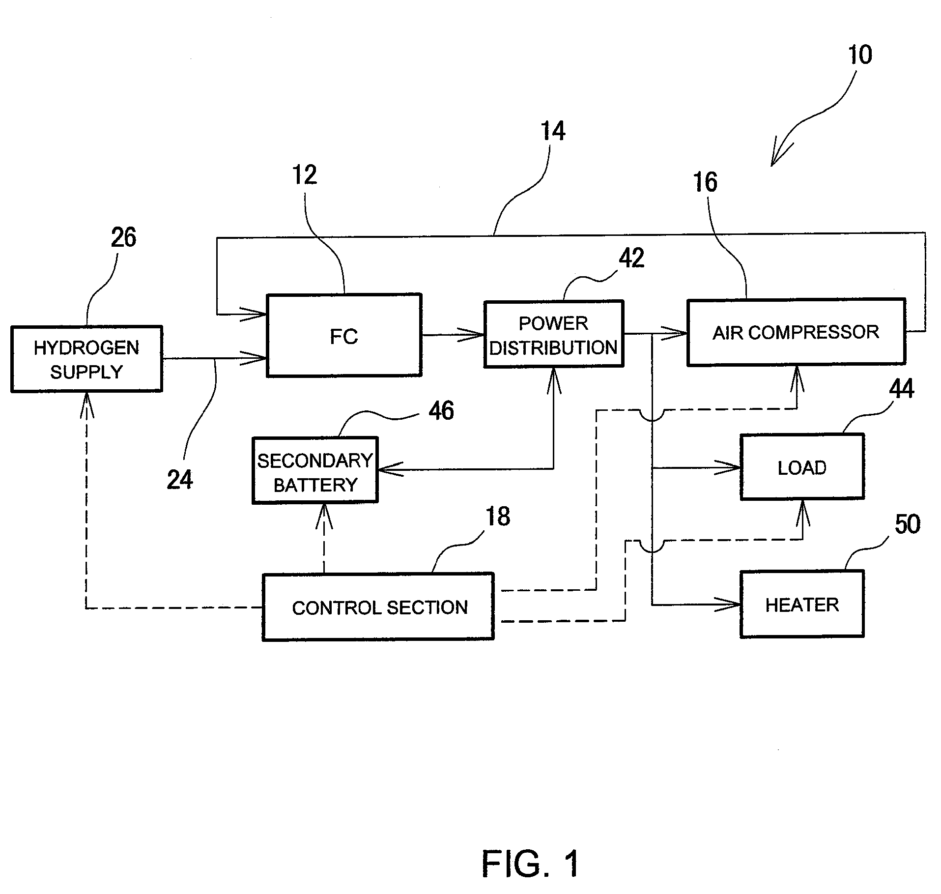
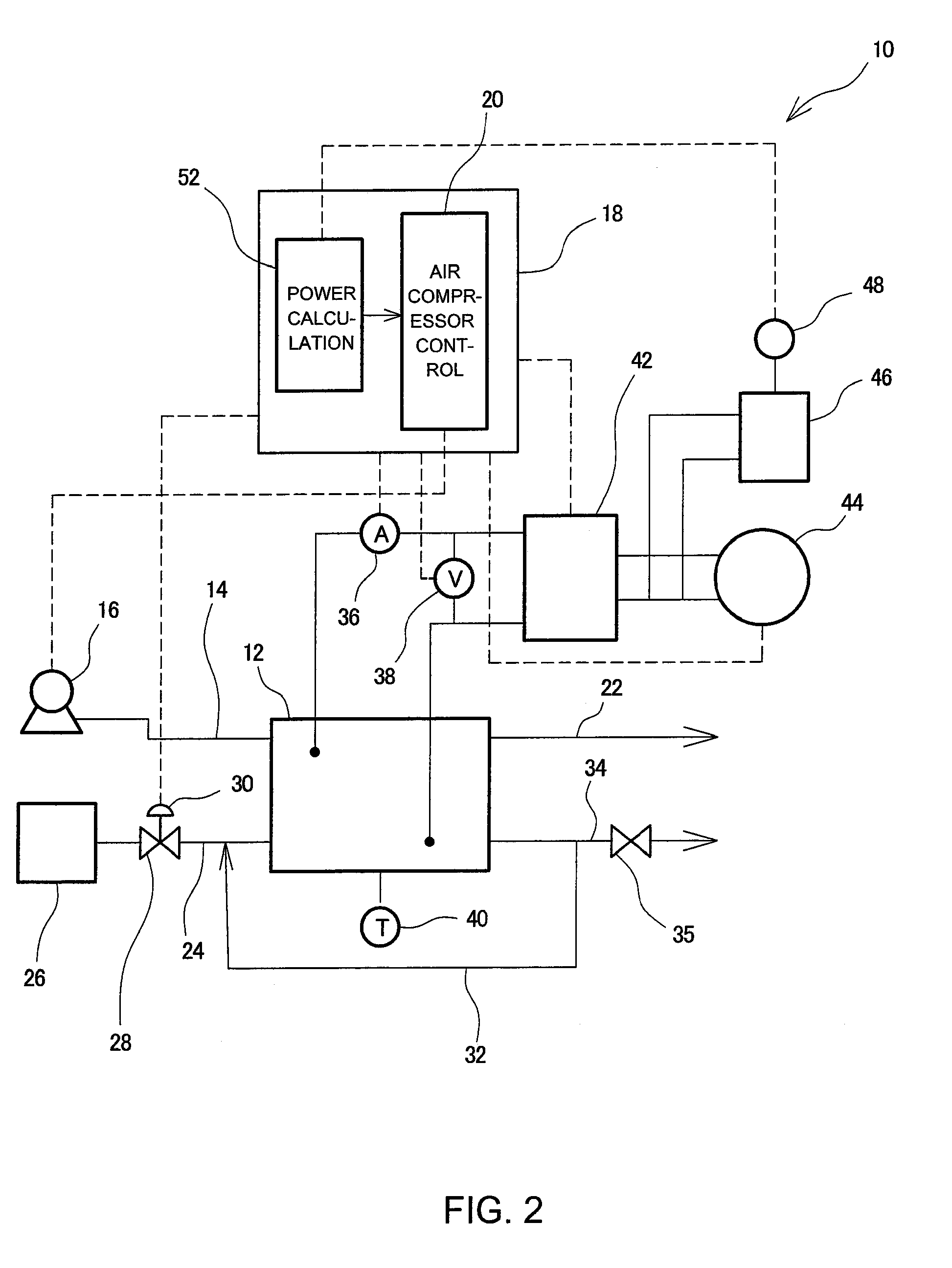
[0020]Embodiments related to the present invention are explained in detail below with reference to the drawings. FIGS. 1-4 and 7 show a first embodiment of the present invention. FIG. 1 is a block diagram showing a basic configuration of a fuel cell system 10 according to the present embodiment, and FIG. 2 is a configuration diagram showing a detailed configuration of the same embodiment.

[0021]The fuel cell system 10 according to the present embodiment is for use by being mounted on a fuel cell vehicle, and includes a fuel cell stack 12. This fuel cell stack 12 includes a fuel cell lamination structure formed by laminating a plurality of fuel cells, and further includes a current collector plate and an endplate provided at each of the two end portions of the fuel cell lamination structure located along the lamination direction. The fuel cell lamination structure, current collector plates, and endplates are clamped together by use of components such as tie rods and nu...

second embodiment

of the Invention

[0059]FIG. 8 is a flowchart that corresponds to FIG. 3, and shows warm-up control processing for warming up a secondary battery at the time of start-up of a fuel cell system according to a second embodiment of the present invention. In the case of the above-described first embodiment, in step S1 of FIG. 3, the control section 18 (FIGS. 1 and 2) judges whether or not the temperature of the fuel cell stack 12 (FIGS. 1 and 2) is equal to or higher than a given temperature, and, depending on the judged result, the processing proceeds to either a shift to normal operation in step S2 (FIG. 3) or to the warm-up control processing from step S3 (FIG. 3) through step S12 (FIG. 3). In contrast, according to the present embodiment, whether to shift to normal operation or to proceed with the warm-up control processing is selected depending on whether the detected temperature of the secondary battery 46 (FIGS. 1 and 2) is equal to or higher than a given temperature. This procedure...


PUM

PropertyMeasurementUnit
electric poweraaaaaaaaaa
charge rateaaaaaaaaaa
power generationaaaaaaaaaa

Abstract

A fuel cell system repeats first processing and second processing when the system is started. In the first processing, a control section controls an electric power distribution section so that electric power generated by a fuel cell stack is supplied to accessories and a secondary battery. In the second processing, the control section controls the electric power distribution section so that electric power generated by the fuel cell stack and electric power discharged from the secondary battery are supplied to the accessories. An electric power calculation means of the control section calculates electric power generation by the fuel cell stack and inputs an output command, representing electric power, into air compressor drive / control means. The electric power calculation means gradually changes the magnitude of electric power generation by the fuel cell stack, represented by the output command, at the time of transition between the first processing and the second processing.

Description

[0001]This is a 371 national phase application of PCT / JP2007 / 070760 filed 18 Oct. 2007, claiming priority to Japanese Patent Application No. JP 2006-284724 filed 19 Oct. 2006, the contents of which are incorporated herein by reference.TECHNICAL FIELD[0002]The present invention relates to a fuel cell system including a fuel cell that generates electric power via an electrochemical reaction between a fuel gas and an oxidizing gas, as well as an oxidizing gas supply section, a secondary battery, and an electric power distribution section.BACKGROUND ART[0003]A fuel cell system includes a fuel cell that generates electric power via an electrochemical reaction between a fuel gas such as a gas containing hydrogen and an oxidizing gas such as air, an oxidizing gas supply section (i.e., an air compressor or the like) for supplying the oxidizing gas to the fuel cell, and a secondary battery capable of being charged and discharged. When a fuel cell system is to be started in a low-temperature ...

Claims


Application Information

Patent Timeline
Patent Type & Authority Patents(United States)
IPC IPC(8): H01M8/04H01M8/00
CPCH01M8/04201H01M8/04223H01M8/04268H01M8/04626H01M8/04768H01M8/04947H01M8/04619Y02E60/50H01M16/006H01M8/04225Y02E60/10
Inventor MAENAKA, TAKESHI
Owner TOYOTA JIDOSHA KK
Learn More