
Method for manufacturing a conductive grid for attachment to a blister package

a technology of conductive grids and blister packages, which is applied in the field of manufacturing a conductive grid for attachment to a blister package, can solve the problems of system failure, brittle clay coating, and sensitivity to temperature and humidity changes,

Active Publication Date: 2011-05-10
INTELLIGENT DEVICES SEZC
View PDF10 Cites 30 Cited by
  • Summary
  • Abstract
  • Description
  • Claims
  • Application Information

AI Technical Summary

Benefits of technology

The present invention provides a method for manufacturing blister packages with conductive grids that can record the time of rupture of a trace associated with a particular blister. The method involves preparing an electronic tag with microcontroller means, capacitor means, oscillator means, resistor means and diode means, transferring tag identification information to the microcontroller means, installing battery power means to the tag, verifying the integrity of the tag and components carried thereby, printing a predetermined pattern of conductive traces on a substrate, verifying resistance levels associated with the traces, permanently connecting a tag to the grid such that defined connection points of the tag are conductively connected to defined portions of the traces, verifying the integrity of the grid including the conductive traces and tag carried thereby, and connecting a grid to a blister package so that each conductive trace of the grid is in alignment with a selected blister of the package. The technical effect of this invention is that it allows for the recording of the time of rupture of a trace associated with a particular blister, providing more accurate information on the timing of the event.

Problems solved by technology

Cracks can interfere with the electrical continuity of the paths causing the system to malfunction.
In addition, paper is composed of fibres, making its surface irregular and sensitive to changes in temperature and humidity.
The clay coating is brittle and can crack when the paper is bent.
Consequently, Carbon or silver ink paths applied directly to the clay coat could lose their electrical continuity.
However, breakage of the conductive path may occur in other sections of the Grid if pressure is not applied properly.
It also reduces the overall magnitude of resistance by half.
Failure to compare the individual resistors to the grid's reference resistor can introduce multiple undetected expulsion events.
Such changes in resistance could cause the attached tag to record incorrect events.
However, accurate crystal resonators are expensive, as they require time to calibrate to the correct frequency.

Method used


Image

  • Method for manufacturing a conductive grid for attachment to a blister package
  • Method for manufacturing a conductive grid for attachment to a blister package
  • Method for manufacturing a conductive grid for attachment to a blister package

Examples


Embodiment Construction

[0047]Each step in the production of a Med-ic™ ECM Tag is explained in detail. The steps are explained in chronological order and with particular reference to the drawings and representations appended hereto.

Step 1: PCB Printing

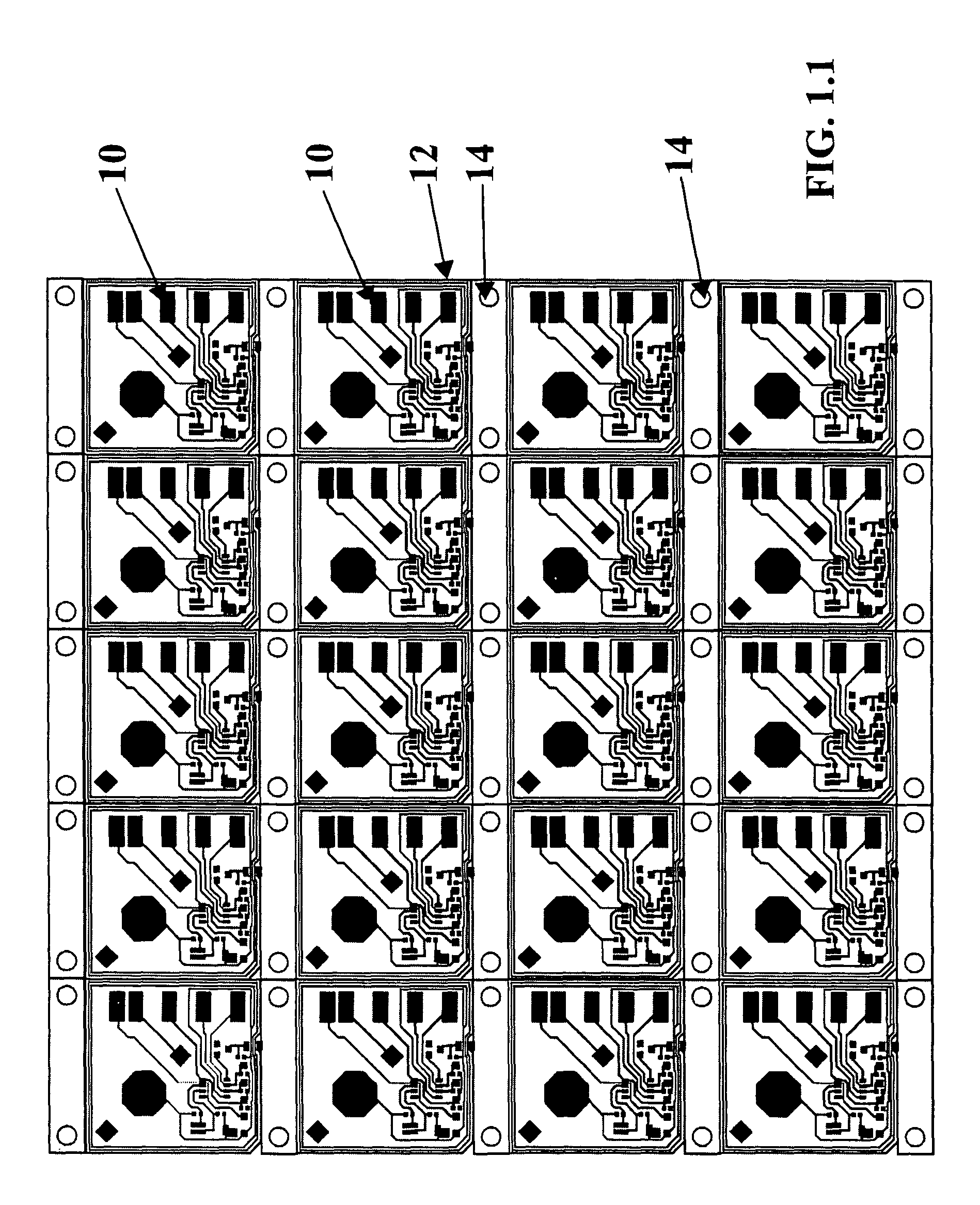
[0048]Printed Circuit Boards (PCB's) 10 are printed on a sheet 12 of suitable flexible substrate in 5-inch×4-inch format. FIG. 1.1 shows a sheet of such PCB's.

[0049]The holes 14 positioned around the periphery of each PCB are used to align the PCB in an automatic soldering machine used to install electronic components on the PCB.

Step 2: Soldering Components on the PCB

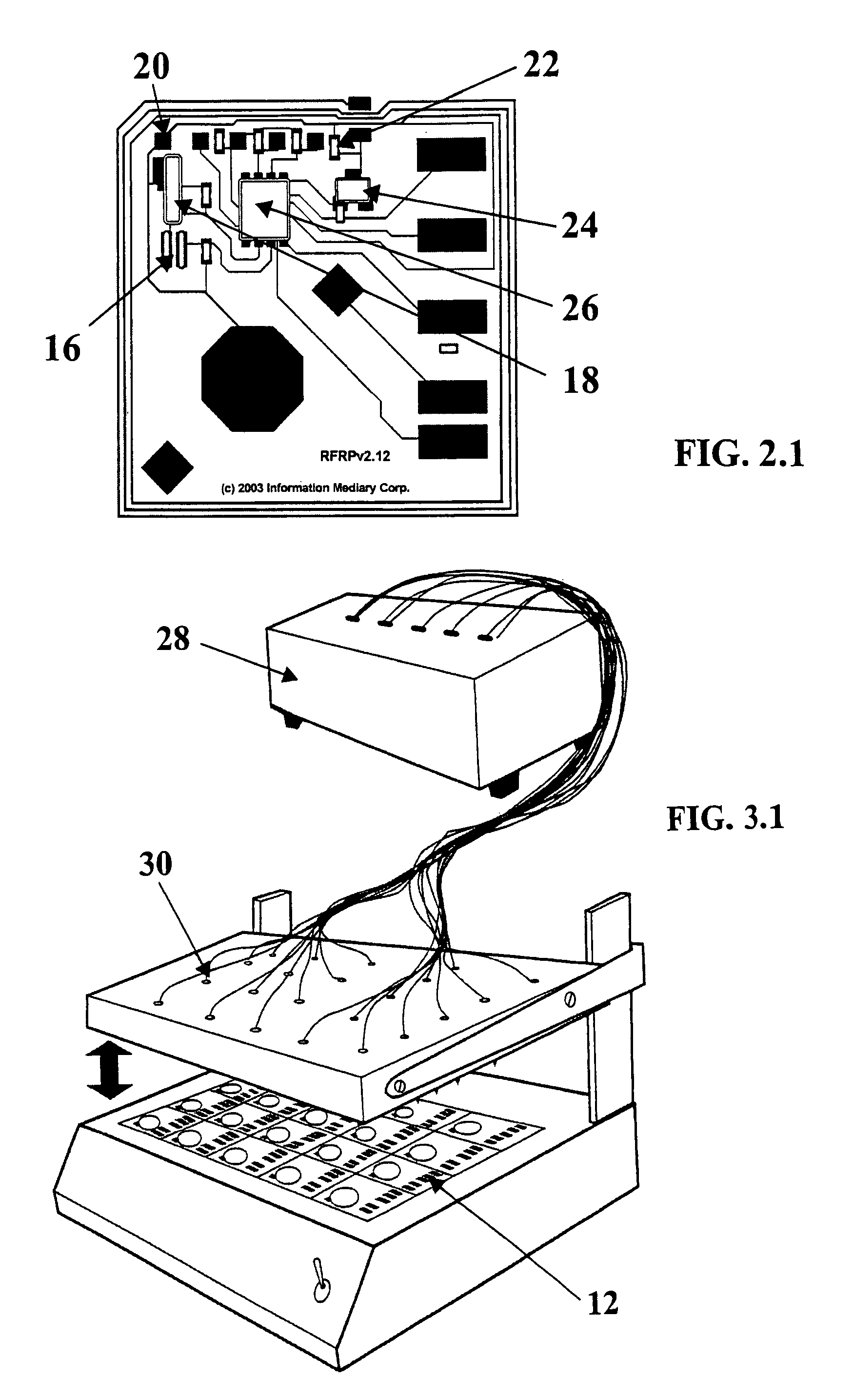
[0050]Electronic components are installed on the PCB 10 using an automated soldering machine. The sheet 12 of PCB's (FIG. 1.1) is placed on the soldering machine's customized jig. The jig has protrusions on its surface that engage the holes 14 and thus permit the sheet of PCB's to be located precisely therein. Once the sheet is in place, the components are soldered to the PCB. FIG. 2.1 shows comp...


PUM

PropertyMeasurementUnit
timeaaaaaaaaaa
conductiveaaaaaaaaaa
electrical poweraaaaaaaaaa

Abstract

The Med-ic™ Electronic Compliance Monitor (ECM) addresses the problem of patient non-compliance with prescribed medication. The Med-ic™ ECM provides precise information about the patient's use of blister-packaged medication in clinical research and general pharmacy settings. Using an on-board central processing unit (CPU), the Med-ic™ ECM records the time each tablet or capsule is expelled from the blister package, keeping a record for later analysis. At the time of refilling or follow-up visit, the information is downloaded to the research assistant's, physician's or pharmacist's computer where it can be displayed graphically. The data can be stored for later analysis. Production of a Med-ic™ ECM Tag involves numerous steps. These steps incorporate certain methods and technologies to accomplish their objective, the steps being detailed in the specification.

Description

[0001]This application is a continuation of international patent application PCT / CA2006 / 00074 filed Jan. 20, 2006 and claims the benefit of Canadian Patent Application Serial Number 2,493,410 filed Jan. 20, 2005.[0002]The present invention relates to the steps involved in the assembly, production and quality assurance processes respecting electronic compliance monitor (ECM) tags, and in particular respecting Med-ic™ tags of Information Mediary Corporation.BACKGROUND OF THE INVENTION[0003]Med-ic™ electronic compliance monitor (ECM) tags are utilized primarily in the pharmaceutical industry in close association with blister packaging of medical items, such as pills or capsules. The pills or capsules are retaining within individual housings of a blister pack, the housings also including a frangible backing sheet through which the pills can be pushed individually as required. Such blister packages are well known. The Med-ic™ ECM tag takes the blister package art a step further in that i...

Claims


Application Information

Patent Timeline
Patent Type & Authority Patents(United States)
IPC IPC(8): H05K3/30G16H20/13
CPCA61J1/035H05K1/0266H05K1/0293H05K1/14H05K1/18H05K2201/09063H05K2201/10037H05K2201/10212H05K2201/10689H05K2203/175Y10T29/49155Y10T29/49169Y10T29/49147Y10T29/4913G16H20/13
Inventor PETERSENWILSON, ALLANSHERSTYUK, MYKOLA
Owner INTELLIGENT DEVICES SEZC
Learn More