Ultrasonic motor
a technology of ultrasonic motors and motors, applied in piezoelectric/electrostrictive/magnetostrictive devices, piezoelectric/electrostriction/magnetostriction machines, electrical equipment, etc., can solve the problems of reducing the life of the motor, reducing the drive efficiency, and the actual fabrication of the ultrasonic motor always involves a machining error, so as to reduce the cost of manufacturing and manufacturing, less machining processes, and good drive efficiency
- Summary
- Abstract
- Description
- Claims
- Application Information
AI Technical Summary
Benefits of technology
Problems solved by technology
Method used
Image
Examples
first embodiment
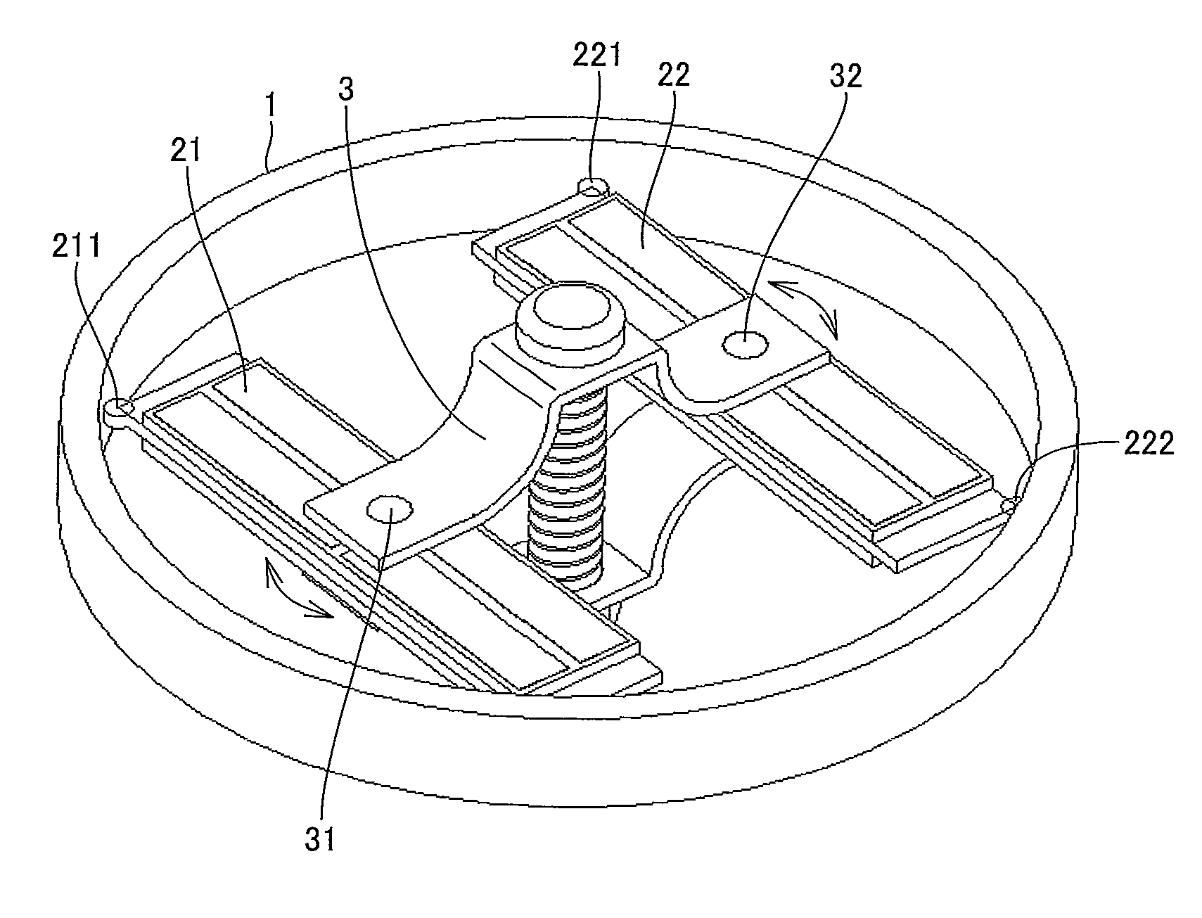
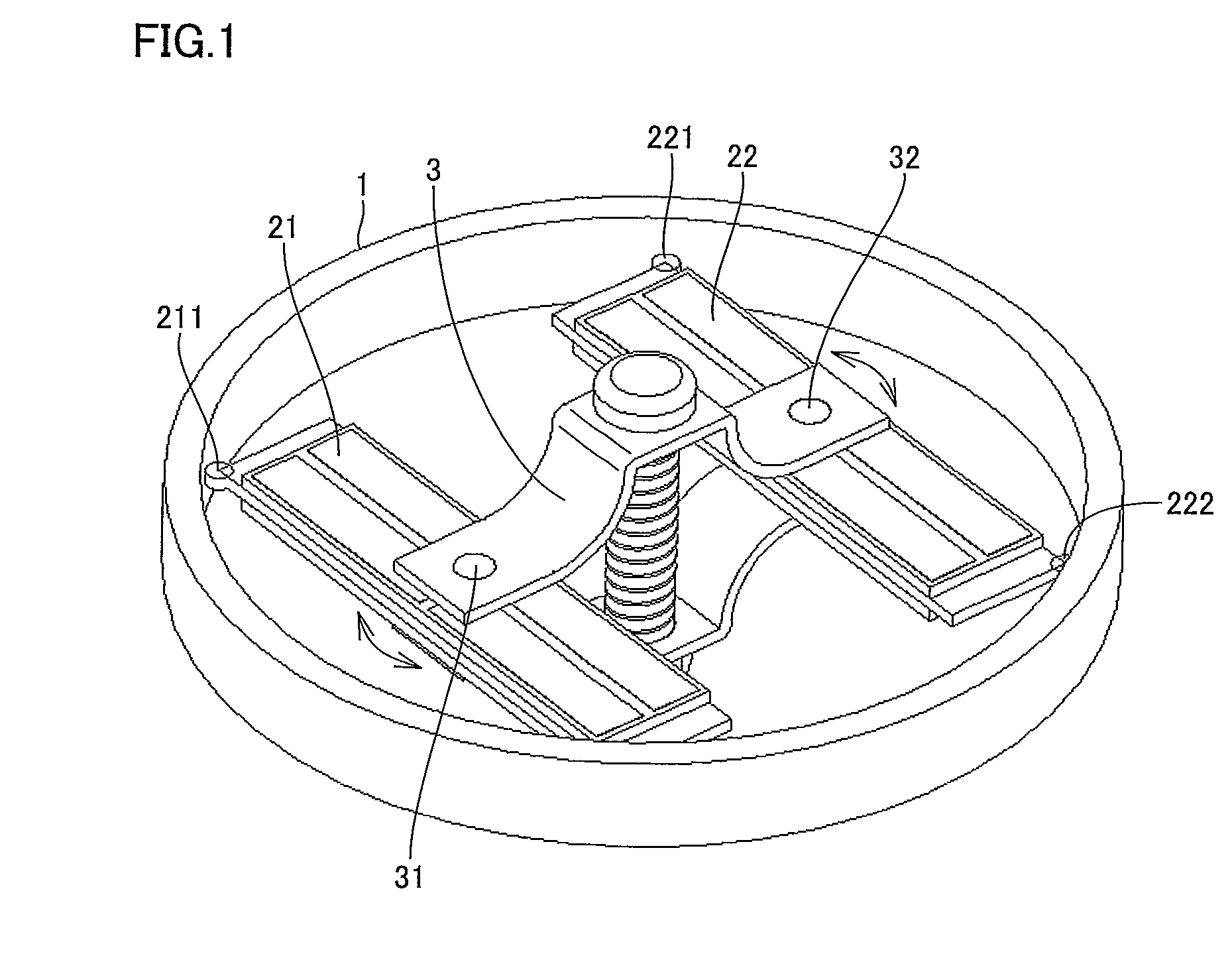
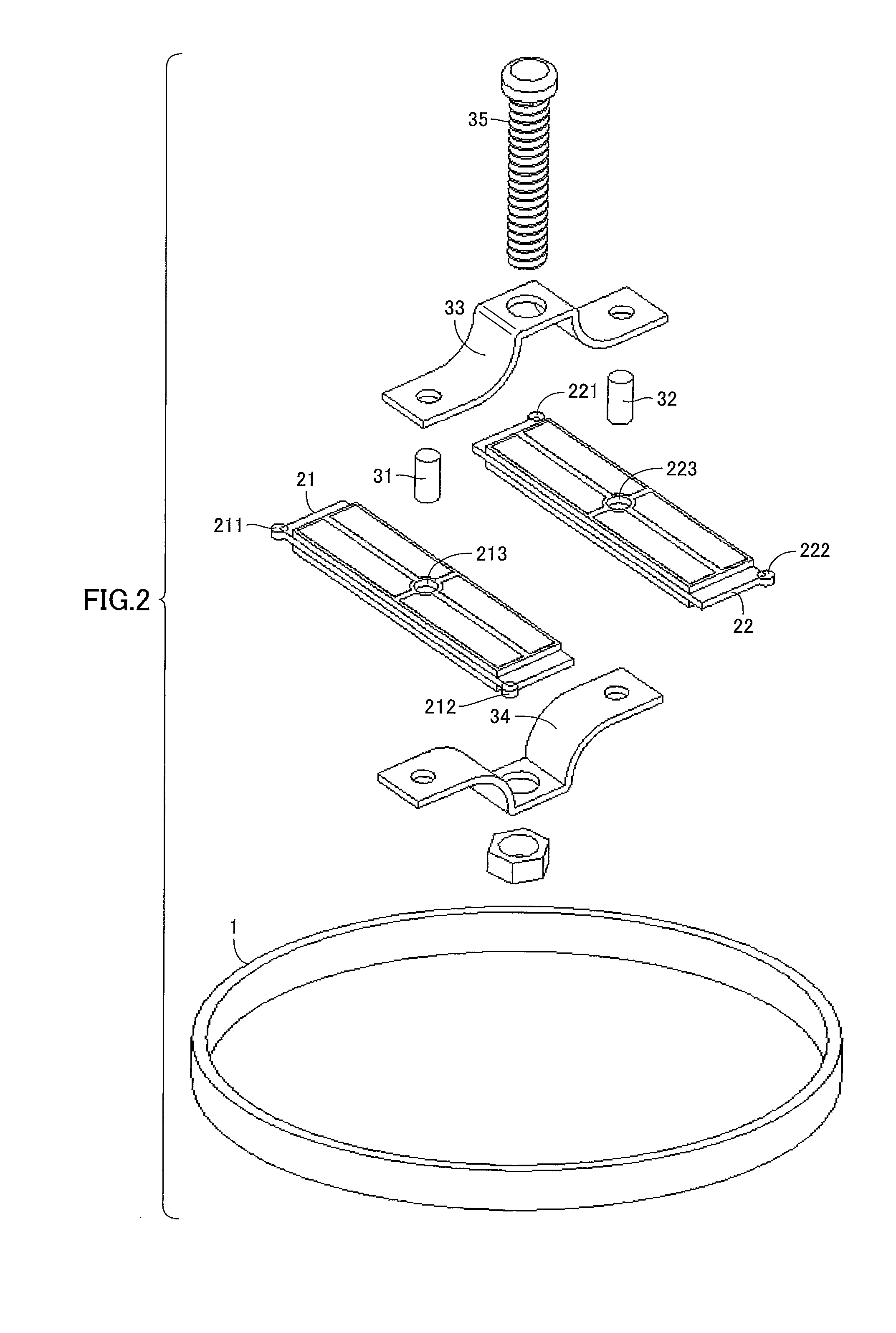
A configuration of an ultrasonic motor of a first embodiment will be described with reference to FIGS. 1 to 4. Two ultrasonic vibrators 21 and 22 are in internal contact with a cylindrical rotor 1 via contact points 211, 212 (not shown), and contact points 221, 222, respectively.
Ultrasonic vibrators 21 and 22 are pressed against rotor 1 by means of preload mechanism 3 to be pushed and expanded outward. Ultrasonic vibrator 21 performs an elliptical motion as described with reference to FIG. 16 by receiving the above-mentioned alternating voltages φA, φB with the phases being shifted by 90°.
Ultrasonic vibrator 22 has a configuration in which electrodes are arranged in mirror symmetry with those of ultrasonic vibrator 21, and performs an elliptical motion as described with reference to FIG. 16 by receiving the above-mentioned alternating voltages φA, φB with the phases being shifted by 90°. That is, all contact points in internal contact with rotor 1 perform the elliptical motion that ...
second embodiment
A configuration of an ultrasonic motor of a second embodiment will be described with reference to FIGS. 5 to 9. For the sake of clarity, components identical to those of the embodiment described above will be designated by the same reference numerals, and the description thereof will not be repeated.
[Overall Configuration]
As shown in FIGS. 5 and 6, ultrasonic vibrators 41 and 42 are configured to be pushed and expanded toward the outside of rotor 1 by means of a pantograph type preload mechanism 43 having projections 431, and are in internal contact with rotor 1. As for the rest, ultrasonic vibrators 41 and 42 are configured in the same way as those in the first embodiment.
[Ultrasonic Vibrators]
Since ultrasonic vibrators 41 and 42 are in mirror symmetry with each other, only ultrasonic vibrator 42 will be described below with reference to FIG. 7. Ultrasonic vibrator 42 has a recess 421 at a central portion of a side surface thereof. This can determine the position of projection 431 ...
PUM
 Abstract
Description
Claims
Application Information
 - R&D
- Intellectual Property
- Life Sciences
- Materials
- Tech Scout
- Unparalleled Data Quality
- Higher Quality Content
- 60% Fewer Hallucinations
Browse by: Latest US Patents, China's latest patents, Technical Efficacy Thesaurus, Application Domain, Technology Topic, Popular Technical Reports.
© 2025 PatSnap. All rights reserved.Legal|Privacy policy|Modern Slavery Act Transparency Statement|Sitemap|About US| Contact US: help@patsnap.com


